Connector and connector device

a technology of connectors and connectors, applied in the direction of coupling devices, coupling contact parts, coupling devices, etc., can solve the problem of entanglement with the requirement of such a high-frequency characteristi

Active Publication Date: 2021-04-22
HIROSE ELECTRIC GROUP
View PDF0 Cites 5 Cited by
  • Summary
  • Abstract
  • Description
  • Claims
  • Application Information

AI Technical Summary

Benefits of technology

[0007]A connector device includes: a plug connector including a plurality of plug terminals, a plug housing that holds the plurality of plug terminals in its longitudinal direction, and a plug shell held by the plug housing; and a receptacle connector including a plurality of receptacle terminals, a receptacle housing that holds the receptacle terminals along its longitudinal direction, and a receptacle shell held by the receptacle housing. The plug shell includes a plug shell plane facing the receptacle connector when the connectors are fitted to each other, a plate-like first plug shield extending in the longitudinal direction of the plug housing, a plate-like second plug shield extending in a short direction of the plug housing, a plug housing support portion held by the plug housing, and a plug shell mounting portion connected to a ground potential of a substrate, the first plug shield faces the plug terminals in the short direction, the receptacle shell includes a receptacle shell plane facing the plug connector wh

Problems solved by technology

One of factors that hinder the requirement for such a high-frequency characteristic is so-called electromagn

Method used


Image

  • Connector and connector device
  • Connector and connector device
  • Connector and connector device

Examples


Embodiment Construction

[0017]In the following detailed description, for purpose of explanation, numerous specific details are set forth in order to provide a thorough understanding of the disclosed embodiments. It will be apparent, however, that one or more embodiments may be practiced without these specific details. In other instances, well-known structures and devices are schematically shown in order to simplify the drawing.

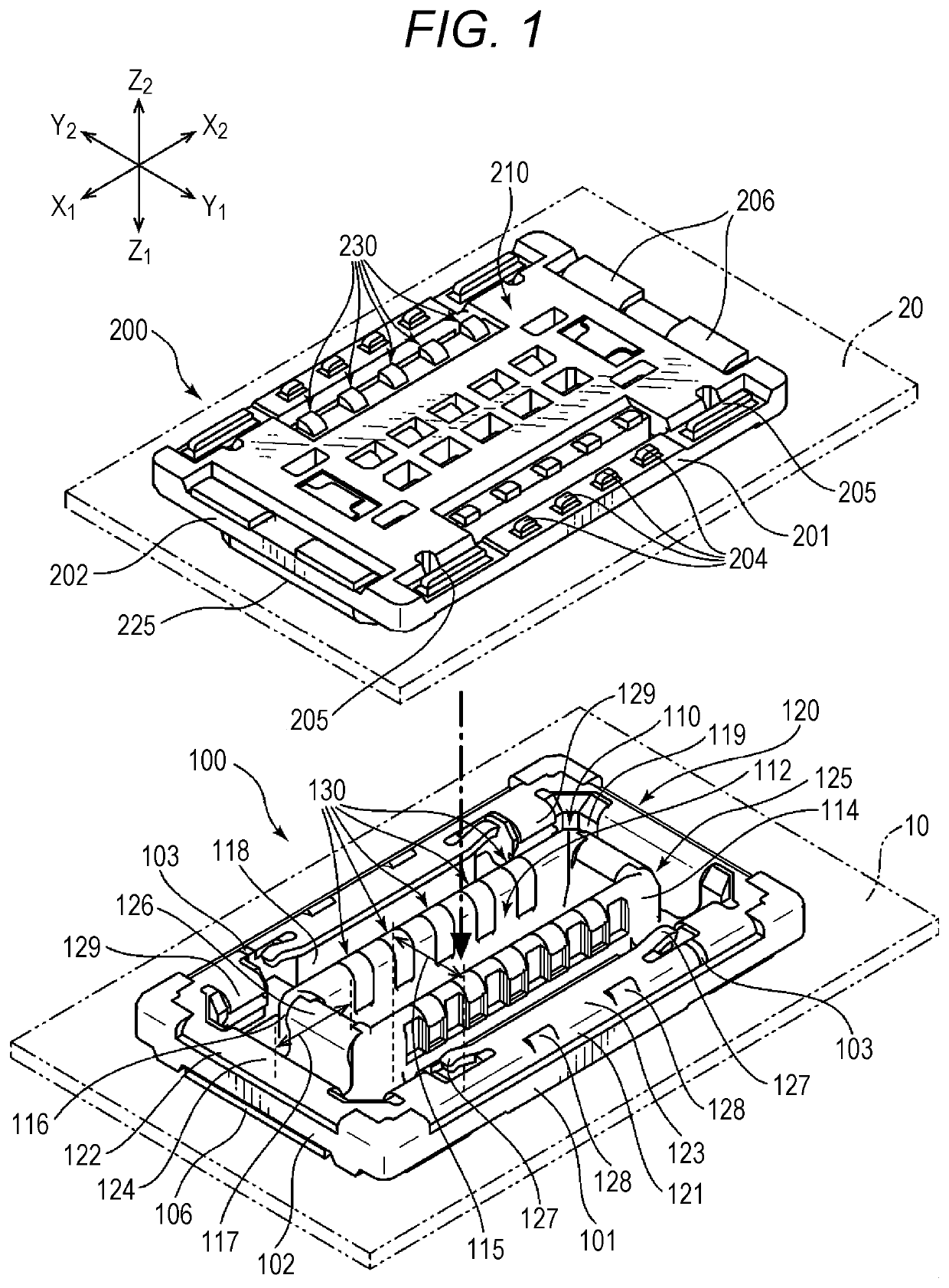
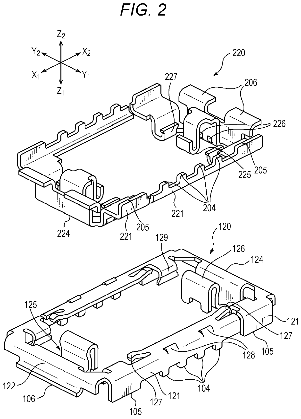
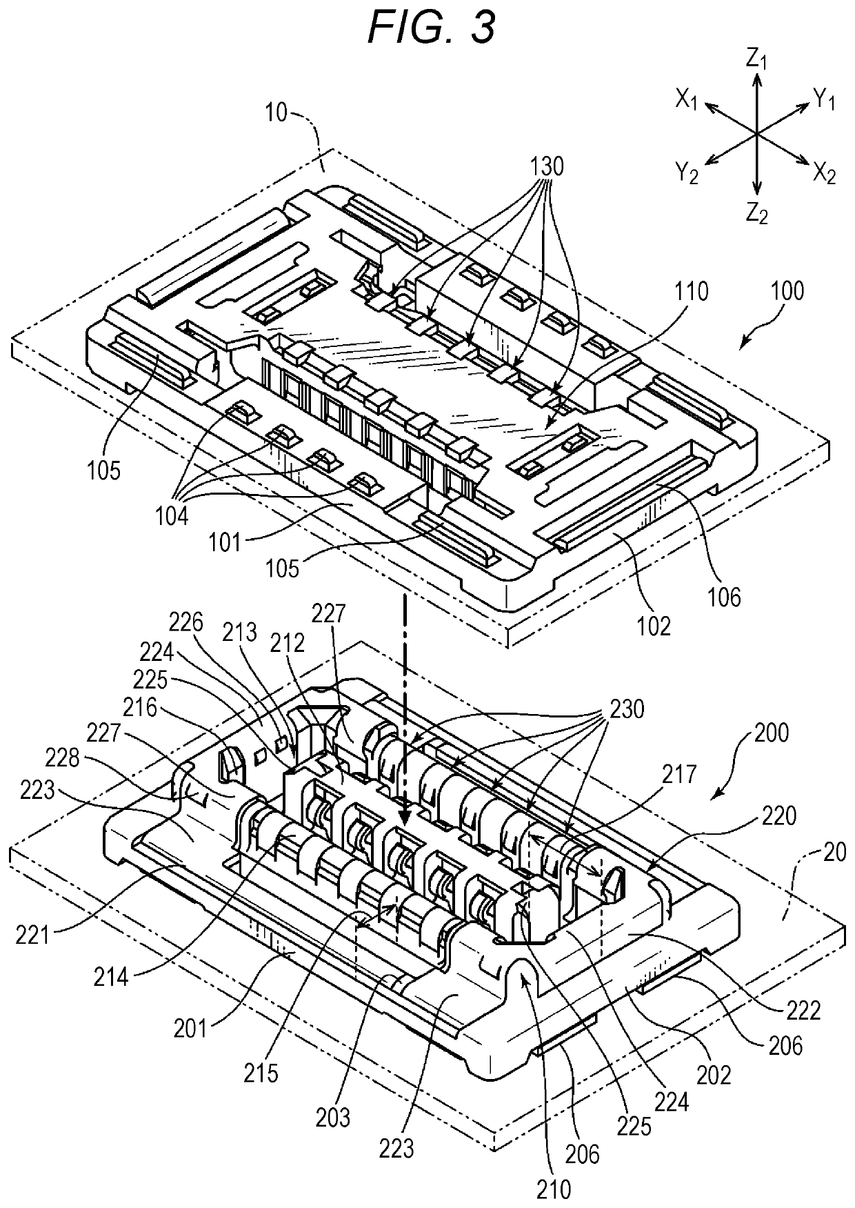
[0018]In general, as electronic devices such as smartphones and mobile terminals have been smaller and more sophisticated, components such as connectors for connecting elements and substrates in a printed wiring board have been more highly densely mounted. There is also a demand for miniaturization of the connector itself that is the component. However, in the conventional connector device, shield wall portions that are provided to extend in a longitudinal direction of the connectors are doubly arranged inside and outside when the connectors are fitted to each other. Due to this doub...


PUM


Abstract

A connector device includes: a plug connector including a plurality of plug terminals, a plug housing that holds the plurality of plug terminals in its longitudinal direction, and a plug shell held by the plug housing; and a receptacle connector including a plurality of receptacle terminals, a receptacle housing that holds the receptacle terminals along its longitudinal direction, and a receptacle shell held by the receptacle housing. The plug shell and the receptacle shell are electrically connected to each other through at least the contact portion in a state where the plug connector and the receptacle connector is fitted with each other.

Description

CROSS-REFERENCE TO RELATED APPLICATION[0001]This application claims priority from Japanese Patent Application No. 2019-189097 filed with the Japan Patent Office on Oct. 16, 2019, the entire content of which is hereby incorporated by reference.BACKGROUND1. Technical Field[0002]One aspect of the present disclosure relates to a connector and a connector device.2. Related Art[0003]The connector device has, for example, a rectangular housing, and a plug-side connector (plug connector) and a receptacle-side connector (receptacle connector) that connect substrates together. A plurality of terminals is arranged in two rows in the housing in its longitudinal direction by insert molding (integral molding) or the like. Such a connector device is disclosed in, for example, JP-A-2017-033909.[0004]The plug connector and the receptacle connector can be provided on a printed wiring board, a flexible flat cable, or the like. For example, the receptacle connector provided on the printed wiring board ...

Claims


Application Information

Patent Timeline
IPC IPC(8): H01R13/6582H01R13/11H01R24/60
CPCH01R13/6582H01R24/60H01R13/112H01R13/113H01R12/73H01R12/716H01R13/6585H01R13/6594H01R13/20H01R13/6581H01R13/2407H01R13/6583H01R12/71H01R12/712
Inventor LEE, YONGJINSUNAGA, SHIRO
Owner HIROSE ELECTRIC GROUP
Why Eureka
Try Eureka