Position sensor and position detection method

a technology of position sensor and position detection, which is applied in the direction of cycle equipment, program control, instruments, etc., can solve the problems of inability and failure to detect the occurrence of anomalies in the sensor

Active Publication Date: 2021-08-19
TOYO DENSO
View PDF0 Cites 0 Cited by
  • Summary
  • Abstract
  • Description
  • Claims
  • Application Information

AI Technical Summary

Benefits of technology

[0008]Accordingly, an object of the present invention is to solve the abovementioned problem that it is impossible to detect occurrence of an anomaly in a position sensor that can detect positions in a plurality of movement ranges of a moving body.
[0011]With the configurations as described above, the present invention makes it possible to detect occurrence of an anomaly in a position sensor that can detect positions in a plurality of movement ranges of a moving body.

Problems solved by technology

However, the accelerator opening detection device disclosed by Patent Document 1 mentioned above may fail to detect occurrence of an anomaly in the sensor.
Then, in a case where the principles of the above accelerator opening detection device are applied not only to a handle grip from which a rotation angle is detected but also to a position sensor configured to detect positions in a plurality of movement ranges of a moving body to be detected, it is also impossible to detect occurrence of an anomaly in the sensor as described above.

Method used


Image

  • Position sensor and position detection method
  • Position sensor and position detection method
  • Position sensor and position detection method

Examples


first example embodiment

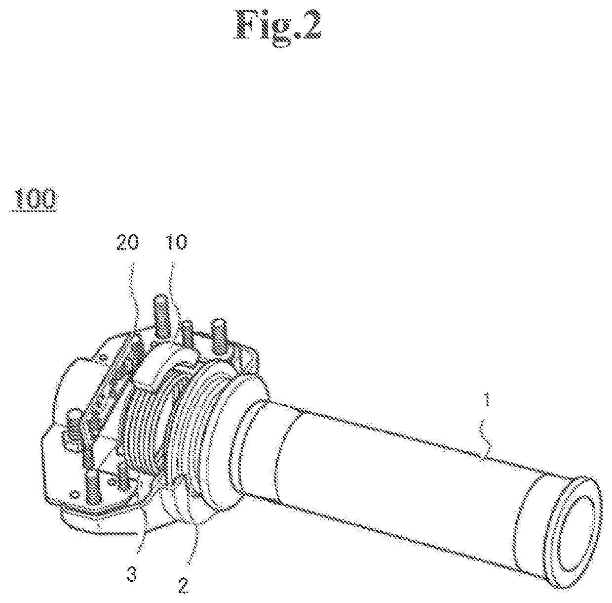
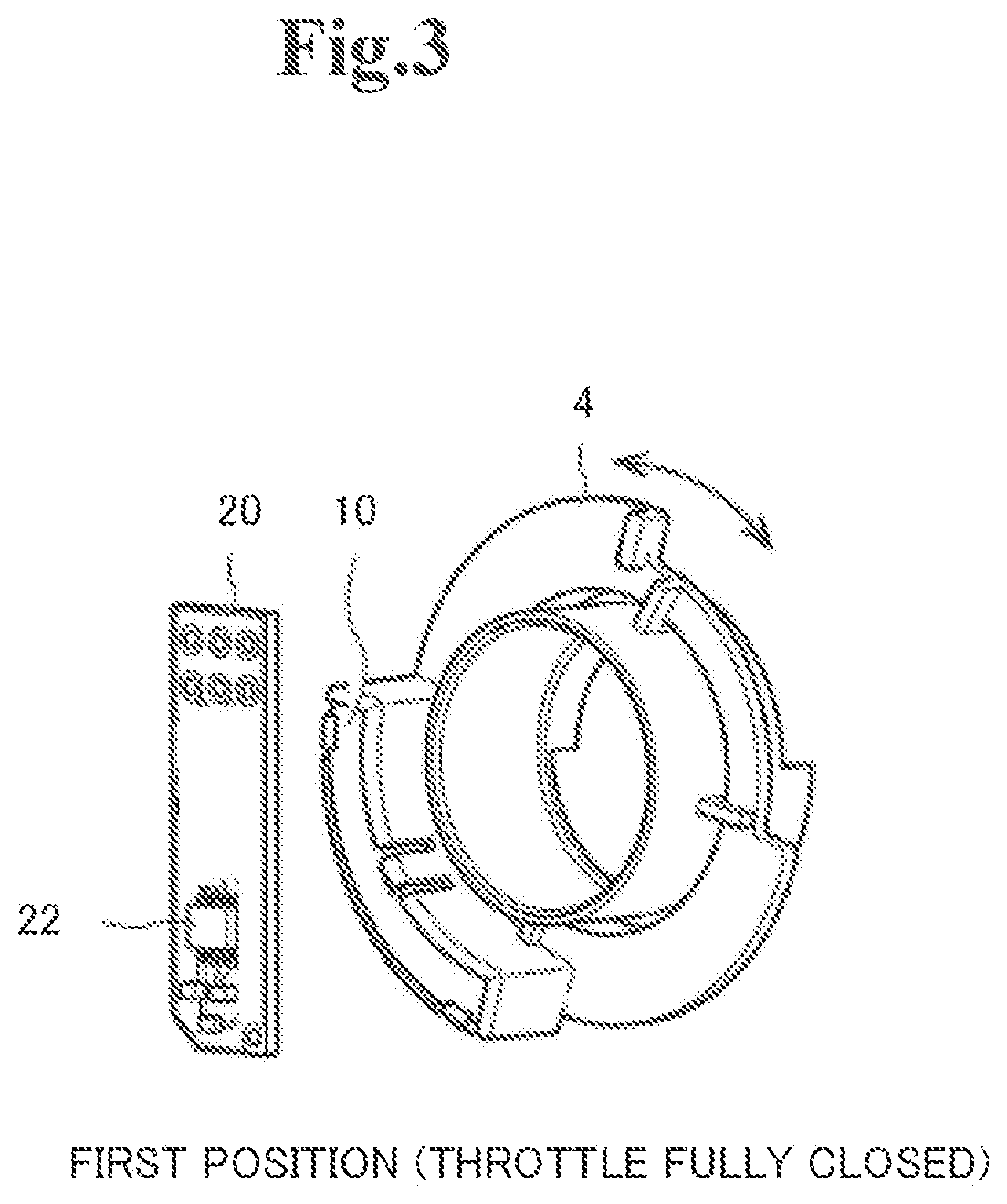
[0023]A first example embodiment of the present invention will be described with reference to FIGS. 1 to 10. FIGS. 1 to 6 are views for describing a configuration of a position sensor, and FIG. 7 is a view for describing an operation of the position sensor. FIGS. 8 to 10 are views for describing other configurations of the position sensor.

Configuration

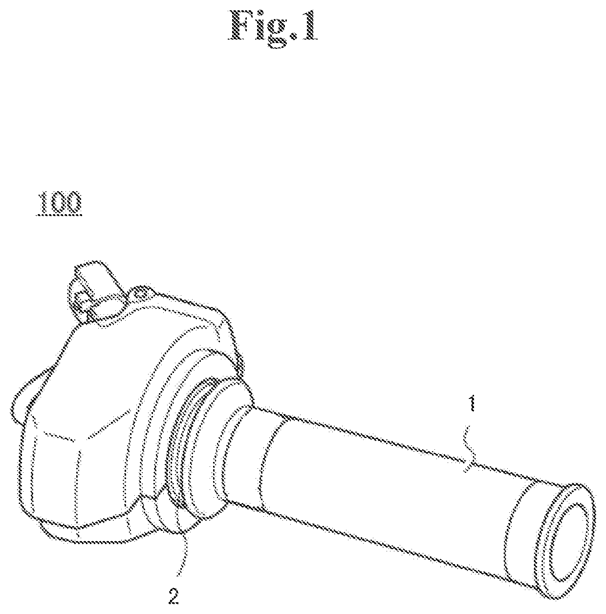
[0024]The position sensor in this example embodiment is a device for detecting the degree of rotation, that is, a rotation position in a rotation direction (a position) of a rotating body. Specifically, as shown in FIG. 1, the position sensor in this example embodiment is mounted on a throttle device 100 for operating an accelerator of a motorcycle and is for detecting the rotation angle of a throttle grip 1. The position sensor in this example embodiment also has a function to detect occurrence of an anomaly in the position sensor. However, the position sensor according to the present invention is not necessarily limited to being moun...

modification example

[0052]In the above description, a case in which as the relation between the detection values detected by the first sensor 21 and the second sensor 22, a relation such that in the case of the rotation angle of the magnet 10 being identical, both the detection values are substantially identical values, that is, both the detection values are values on the identical loci L1 and L2 as shown in FIG. 6 is set by the functions of the amplifiers 23 and 24 has been illustrated. Meanwhile, another relation may be set. For example, as shown in FIG. 8, as the relation between the detection values detected by the first sensor 21 and the second sensor 22, a relation such that the detection values are values on the mutually parallel loci L1 and L2 may be set by the functions of the amplifiers 23 and 24. In other words, although the loci L1 and L2 do not coincide, the change rates of the respective detection values are set to be identical in each of the abovementioned sections. To be specific, in th...


PUM

PropertyMeasurementUnit
rotation angleaaaaaaaaaa

Abstract

A position sensor of the present invention includes: a magnet that moves together with a moving body; a magnetic sensor that detects a magnetic flux generated by the magnet; and a detector that detects an anomaly of the magnetic sensor based on a detection value detected by the magnetic sensor. The magnetic sensor is set so as to detect the detection value taking a value on a locus preset in accordance with a position of the moving body, and the locus is set so that a change rate of the detection value corresponding to change of the position of the moving body differs for each of a plurality of sections set within a movement range of the moving body. The detector detects the anomaly of the magnetic sensor based on a relation between the detection value and a comparison value that is a value corresponding to the locus.

Description

INCORPORATION BY REFERENCE[0001]The present invention is based upon and claims the benefit of priority from Japanese patent application No. 2020-022978, filed on Feb. 14, 2020, the disclosure of which is incorporated herein in its entirety by reference.TECHNICAL FIELD[0002]The present invention relates to a position sensor and a position detection method for detecting the position of a moving body.BACKGROUND ART[0003]On a motorcycle, a driver mainly rotates a throttle grip and thereby adjusts an accelerator opening to operate an accelerator. An accelerator opening is detected by detection of the rotation angle of a throttle grip. Meanwhile, in recent years, an accelerator opening is often detected by detection of a magnetic flux generated by a magnet rotating together with a throttle grip by a magnetic sensor.[0004]Patent Document 1 discloses an example of an accelerator opening detection device that detects an accelerator opening by using a magnetic sensor. The accelerator opening ...

Claims


Application Information

Patent Timeline
Patent Type & Authority Applications(United States)
IPC IPC(8): F02D31/00G01D5/14
CPCF02D31/007F02D2200/0404G01D5/14G01D5/145G01D3/08F02D11/02B62K23/04B62J45/413B60W2420/503G05B2219/37094G01R15/20G05B2219/25272G01R33/07
Inventor KISHI, SHOJIYOSHIDA, TOSHIYAOTANI, TAKAYUKIMURATA, TOSHIKAZU
Owner TOYO DENSO
Why Eureka
Try Eureka