
Secure upstream transmission in passive optical networks

a passive optical network and upstream traffic technology, applied in the field of communication networks and optical transmission technology, can solve the problems of epon privacy and confidentiality problems, upstream traffic from any given onu may be detectable from other onu access points, and remove security problems, so as to avoid delay in data transmission, simplify the method and system according to some embodiments, and save processing performance in the onus

Active Publication Date: 2009-09-22
SCHOFIELD TECH
View PDF15 Cites 2 Cited by
  • Summary
  • Abstract
  • Description
  • Claims
  • Application Information

AI Technical Summary

Benefits of technology

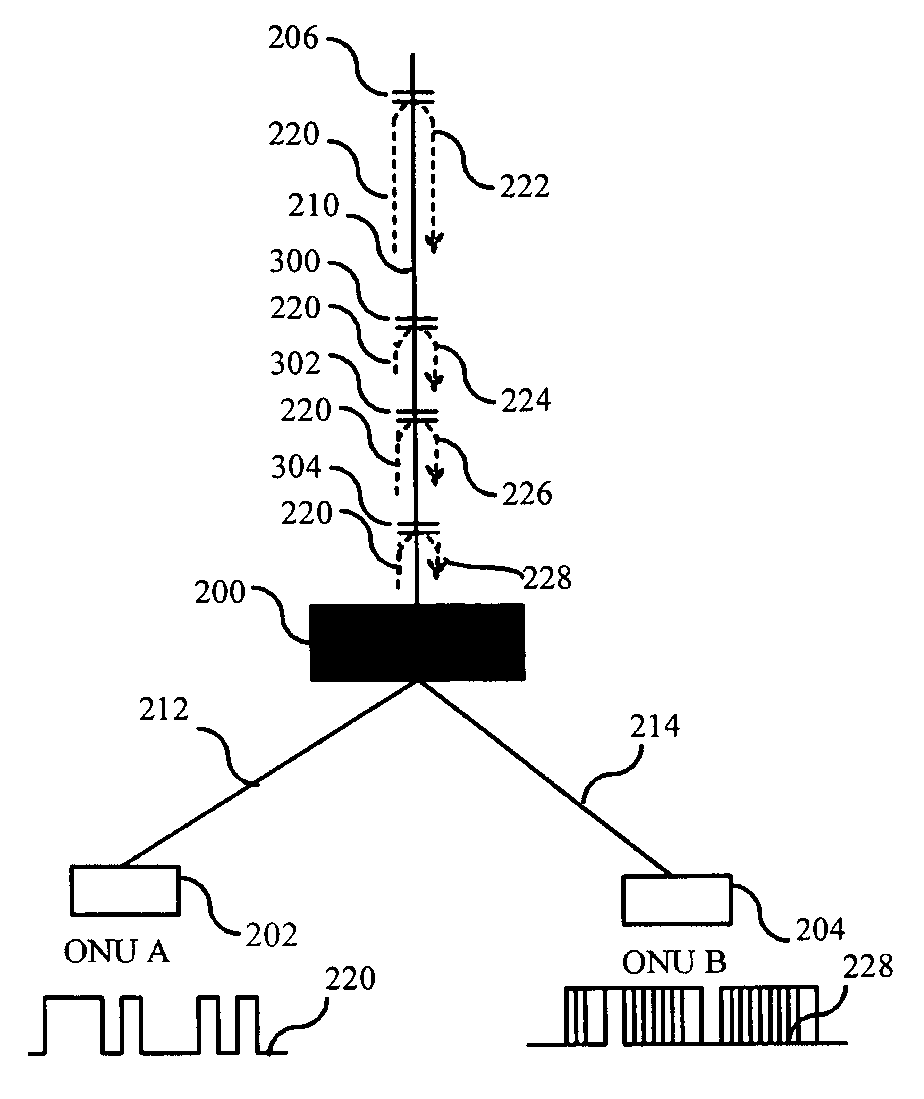
"The invention provides a method and system for ensuring secure and confidential upstream data transmission in Ethernet passive optical networks. This is achieved by using a disturbing reflector placed upstream of a station and a possible point of eavesdropping to produce a disturbing reflection that combines with a second reflection of the signal transmitted by the station. This combination makes the detection of the unwanted reflection impossible. The invention simplifies the process and saves processing performance in the optical network units. It also avoids delay in data transmission and simplifies or omits key exchange before data transmission."

Problems solved by technology

Other option is to have separate fiber for up and downstream but this does not remove the security problem.
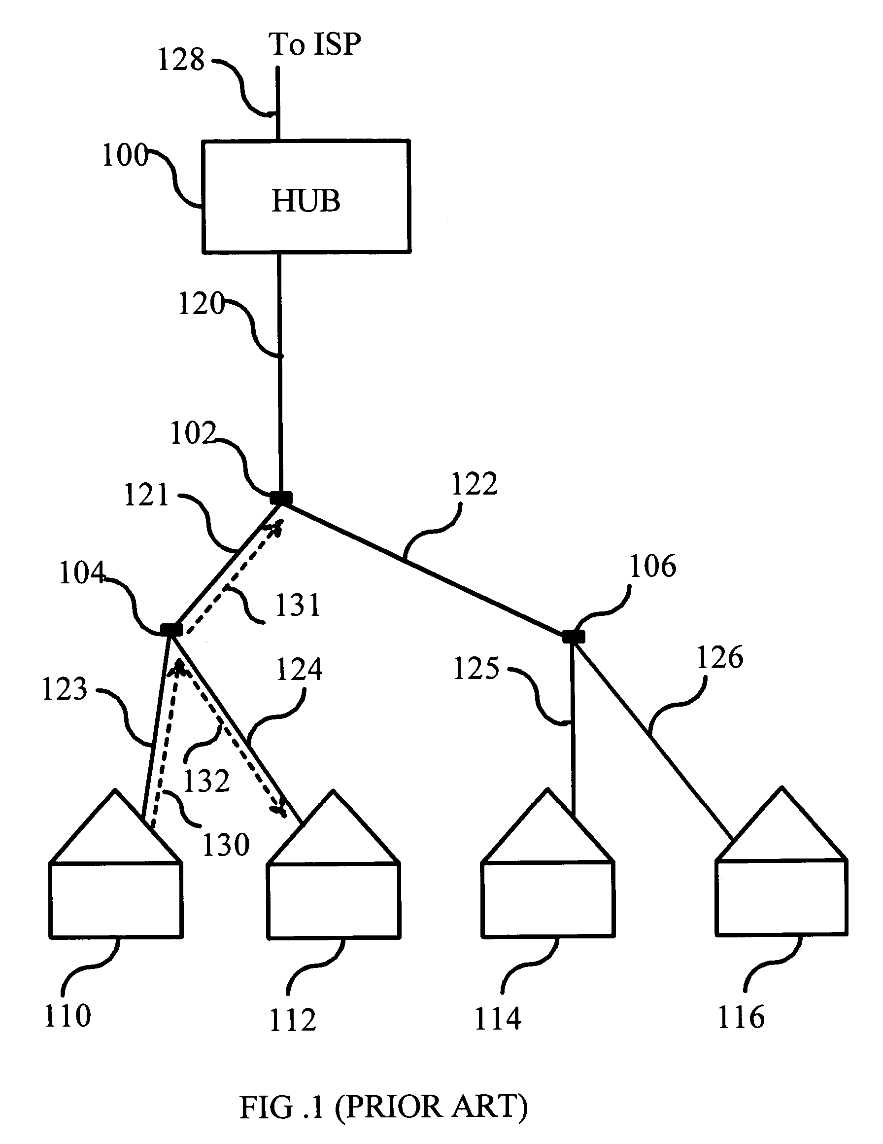
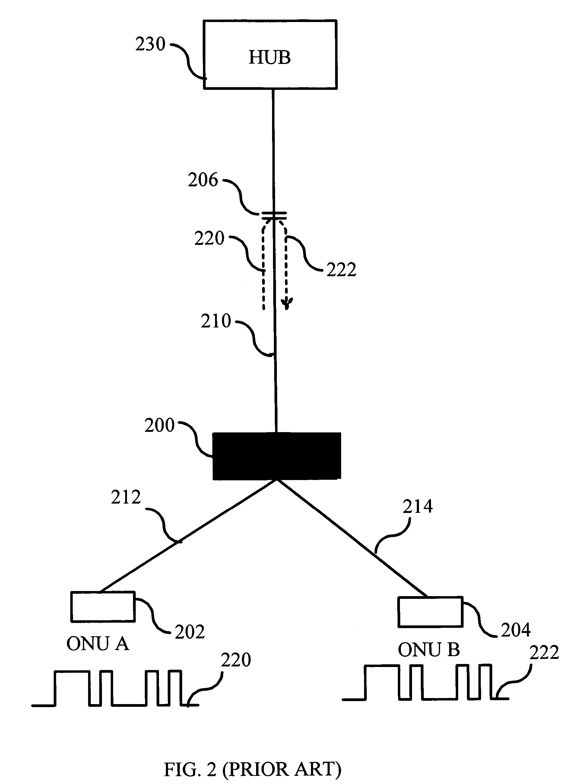
The drawback of the prior art IEEE 802.3ah is that the upstream traffic from any given ONU may be detectable from other ONU access points due to various unwanted signal reflections.
Reflecting elements where discrete back reflections may occur cause privacy and confidentiality problems in EPONs.
The key exchange mechanisms to be used in the case where the upstream connection cannot be regarded as secure, are vastly more complicated compared to the case where the upstream connection can be regarded as reliable.
More complicated mechanisms always leads to the consumption of processing capacity, for example, in ONUs 202, 204, and delays in transmission.
This is a rather expensive solution.

Method used


Image

  • Secure upstream transmission in passive optical networks
  • Secure upstream transmission in passive optical networks
  • Secure upstream transmission in passive optical networks

Examples


Embodiment Construction

[0025]Reference will now be made in detail to the embodiments of the present invention, examples of which are illustrated in the accompanying drawings.

[0026]FIG. 3 illustrates a block diagram depicting an EPON that utilizes one embodiment of the invention. The exemplary EPON includes two ONUs 202, 204. ONUs 202 and 204 are connected to an optical splitter 200 that connects fiber 210 to a fiber 212 and a fiber 214. ONUS 202 acts as the transmitting terminal that is transmitting a signal 220 to fiber 210. ONU 204 is causing a potential confidentiality problem for the transmission, since signal 220 is reflected back from a reflecting element 206 so that the intensity of the reflection permits reception at ONU 204 end of fiber 214. Reflecting element 206 is assumed to be a part of the EPON infrastructure, which cannot be eliminated or is too difficult and / or expensive to eliminate. Besides, its precise location or reflecting quality may be unknown. In accordance with certain embodiments...


PUM


Abstract

A method and system for ensuring confidentiality of signal transmission in a point-to-multi point data transmission network like Ether net passive optical network, including at least one hub, at least one transmission medium and at least one station connected to the hub via the transmission medium. When an upstream signal is transmitted from a first station, the upstream signal is reflected by at least one disturbing reflector for producing a disturbing reflection. The disturbing reflection combines with a second reflection of the upstream signal and renders the second reflection undependable by a second station.

Description

BACKGROUND OF THE INVENTION[0001]1. Field of the Invention[0002]The invention relates to communication networks and optical transmission technology. Particularly, the invention relates to Ethernet passive optical networks and improving security therein using optical disturbing reflectors.[0003]2. Description of the Related Art[0004]In the last few years the requirements for consumer bandwidth have grown rapidly. To meet the demand for increased bandwidth new access network technologies have been developed. One such technology is based on the Institute of Electrical and Electronics Engineers (IEEE) 802.3ah standard. 802.3ah is a trademark of the IEEE Inc. The standard is also known as Ethernet in the First Mile (EFM). The aim of IEEE 802.3ah is to bring Ethernet to ordinary consumers, thereby becoming an alternative for modem dial up lines and DSL connections as the primary access between a consumer and her internet service provider. The IEEE 802.3ah standard also introduces the Ethe...

Claims


Application Information

Patent Timeline
Patent Type & Authority Patents(United States)
IPC IPC(8): H04J14/00H04J3/16H04K1/00
CPCH04K1/00H04J3/1694H04B10/00H04B10/25H04L12/22H04L12/28
Inventor POHJOLA, OLLI-PEKKATERVONEN, ARI
Owner SCHOFIELD TECH
Learn More