Assembled battery

Pending Publication Date: 2022-09-22
PRIME PLANET ENERGY & SOLUTIONS INC
View PDF0 Cites 0 Cited by
  • Summary
  • Abstract
  • Description
  • Claims
  • Application Information

AI Technical Summary

Benefits of technology

The present invention aims to solve the problem of deterioration in the joint part between an electrode terminal and a bus bar due to external load. It provides a technology to suppress such deterioration. It is preferable for the first and second members to be composed of mutually different metals as it tends to causes more deterioration in the metal joint part between the two members. However, by providing a space in the flexible part, it is possible to suppress the thermal deterioration of the metal joint part between the first and second members.

Problems solved by technology

When such an external load acts on the joint part between the electrode terminal and the bus bar, the joint part may be deteriorated, which may result in the reduction of the junction strength, the electric conductivity, or the like.

Method used


Image

  • Assembled battery
  • Assembled battery
  • Assembled battery

Examples


first embodiment

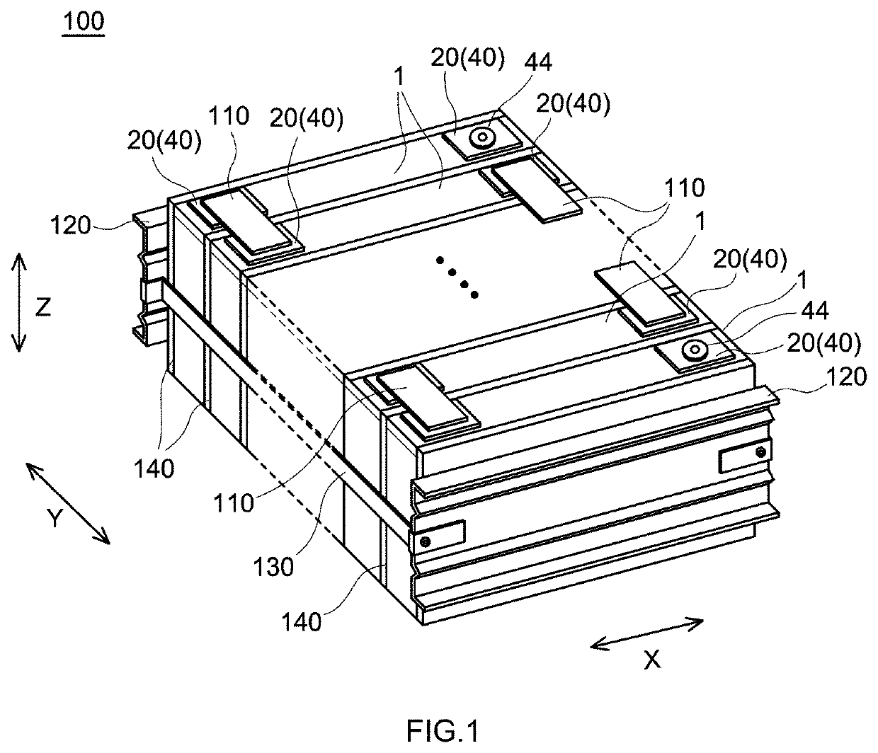
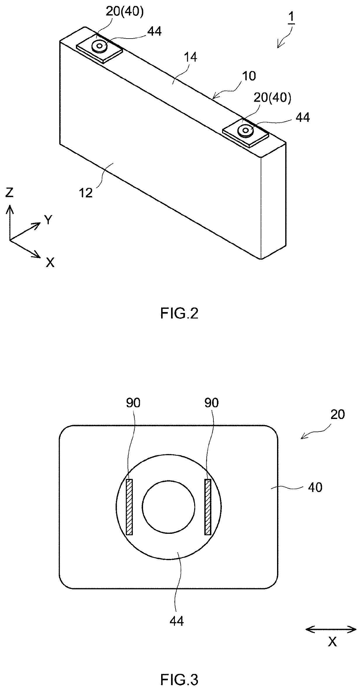
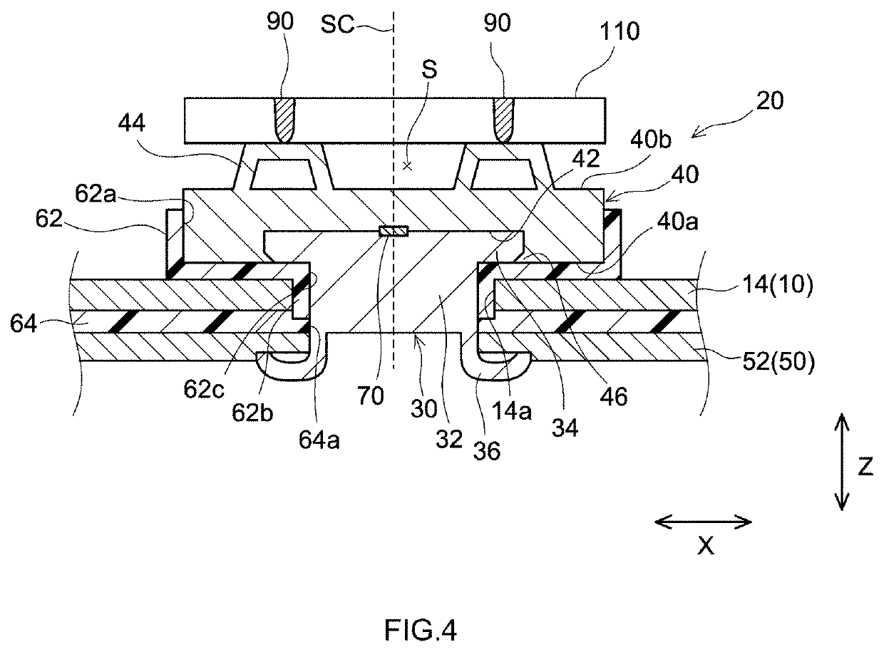
[0025]Below, an assembled battery in accordance with one embodiment (which will be hereinafter referred to as “First Embodiment”) of the technology herein disclosed will be described with reference to FIGS. 1 to 5. FIG. 1 is a perspective view schematically showing an assembled battery in accordance with First Embodiment. FIG. 2 is a perspective view schematically showing a single cell of the assembled battery in accordance with First Embodiment. FIG. 3 is a plan view for schematically illustrating a joint part between an electrode terminal and a bus bar in the assembled battery in accordance with First Embodiment. FIG. 4 is a local cross sectional view for schematically illustrating a joint part between an electrode terminal and a bus bar in the assembled battery in accordance with First Embodiment. FIG. 5 is a cross sectional view for schematically illustrating a configuration of the electrode terminal for use in the assembled battery in accordance with First Embodiment.

[0026]Asse...

second embodiment

[0067]For example, as shown in FIG. 3, in First Embodiment, the flexible part 44 in a planar ring shape was formed at the second member 40. However, the planar shape of the flexible part is not limited thereto. FIG. 6 is a plan view for schematically illustrating the joint part between the electrode terminal and the bus bar in an assembled battery in accordance with Second Embodiment. As shown in FIG. 6, a second member 240 of the electrode terminal 220 in Second Embodiment has a flexible part 244 in a linear shape in a plan view. Specifically, the second member 240 is provided with a pair of linear flexible parts 244 opposed to each other with the shaft part 32 of the first member 30 (see FIG. 4) interposed therebetween. Even in such a planar shape, the flexible part 244 can be properly deformed with respect to an external load. For this reason, it is possible to suppress the application of a strong stress to the joint part 290 between the bus bar and the electrode terminal 220.

third embodiment

[0068]Further, the flexible part may only protrude toward the bus bar, and is also not required to have the cross sectional structure as described in the First Embodiment. Specifically, in First Embodiment, there is provided the flexible part 44 including the space 44c surrounded by the flat part 44a, the wall parts 44b, and the second surface 40b formed in the inside thereof. The electrode terminal 20 with such a configuration is formed by, for example, welding the flexible part 44 to the second surface 40b of the sheet-shaped second member 40. However, the cross sectional structure of the flexible part is not limited thereto. FIG. 7 is a cross sectional view for schematically illustrating the electrode terminal for use in an assembled battery in accordance with Third Embodiment. As shown in the FIG. 7, for an electrode terminal 320 in Third Embodiment, a flexible part 344 is formed by bending a sheet-shaped second member 340. The flexible part 344 in Third Embodiment has a flat pa...


PUM


Abstract

A technology is provided which suppresses the deterioration of the joint part between the electrode terminal and the bus bar due to an external load. An assembled battery herein disclosed includes a plurality of single cells, and a bus bar. The plurality of single cells each include an electrode body, a battery case, and an electrode terminal. The electrode terminal in at least one single cell among the plurality of single cells includes a first member having one end arranged outside the battery case, and the other end arranged inside the battery case, and a second member arranged at the outer surface of the battery case, and mounted at the end of the first member. Herein, a flexible part protruding toward the bus bar is formed at the surface of the second member, and the electrode terminal is joined with the bus bar at the flexible part.

Description

CROSS REFERENCE TO RELATED APPLICATIONS[0001]The present application claims the priority based on Japanese Patent Application No. 2021-047151 filed on Mar. 22, 2021, the entire contents of which are incorporated by reference in the present specification.BACKGROUND OF THE DISCLOSURE1. Technical Field[0002]The present invention relates to an assembled battery.2. Background[0003]Currently, a secondary battery such as a lithium ion secondary battery or a nickel hydrogen battery has been widely used in various fields including a vehicle, a portable terminal, and the like. Such a secondary battery generally includes an electrode body which is a power generating element and a battery case for accommodating the electrode body. Further, for such a secondary battery, such a structure is adopted, which leads out the electrode terminal connected with the electrode body inside the battery case to outside the case. Then, the secondary battery of the foregoing structure can be mounted on a vehicle...

Claims


Application Information

Patent Timeline
IPC IPC(8): H01M50/562H01M50/505
CPCH01M50/562H01M50/505H01M50/552H01M50/507H01M50/516Y02E60/10H01M50/172H01M50/564
Inventor SAKURAI, TAKAHIRO
Owner PRIME PLANET ENERGY & SOLUTIONS INC
Why Eureka
Try Eureka