Automotive Heater Core

a heater core and heater core technology, applied in the direction of heat exchanger fastening, lighting and heating apparatus, stationary conduit assemblies, etc., can solve the problems of leakage and failure of the heater core, affecting the effective cooling area, appearance and quality of products, and comparatively low overall angular rigidity of the heater core. , to achieve the effect of good brazing, increased friction between the cooling fins and side plates, and firm bonding

Inactive Publication Date: 2009-07-30
XU HUIXIN
View PDF6 Cites 1 Cited by
  • Summary
  • Abstract
  • Description
  • Claims
  • Application Information

AI Technical Summary

Benefits of technology

[0011]1. The clamping of clinching tabs to the edges of the tanks structurally ensures the mechanical strength of the connection between the header to the upper tank and to the bottom tank. It ensures a good brazing and firm bonding between the tanks and the header.
[0012]2. By adding the button protuberances or the retaining tabs, the cooling fins are kept from touching the header and the friction bet...

Problems solved by technology

The shortages of old art are:1. Brazing between the header and tank is not firm, which causes leak and failure of a heater core2. During the brazing process, as the materials used for cooling fins and header plate are different, they require different temperature of brazing, thus the cooling fins are often melted where they contact the header, which affects negatively the effective cooling area and the appearance and quality of the products, and often the cooli...

Method used


Image

  • Automotive Heater Core
  • Automotive Heater Core
  • Automotive Heater Core

Examples


Embodiment Construction

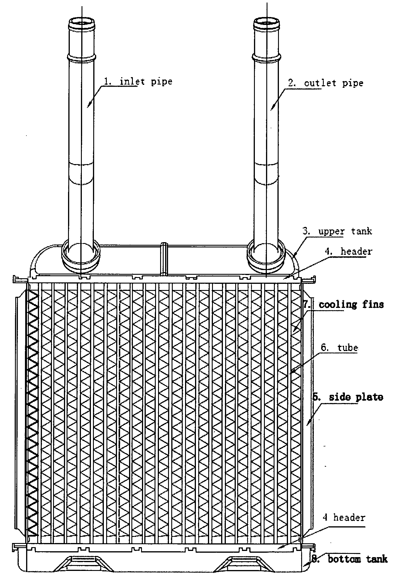
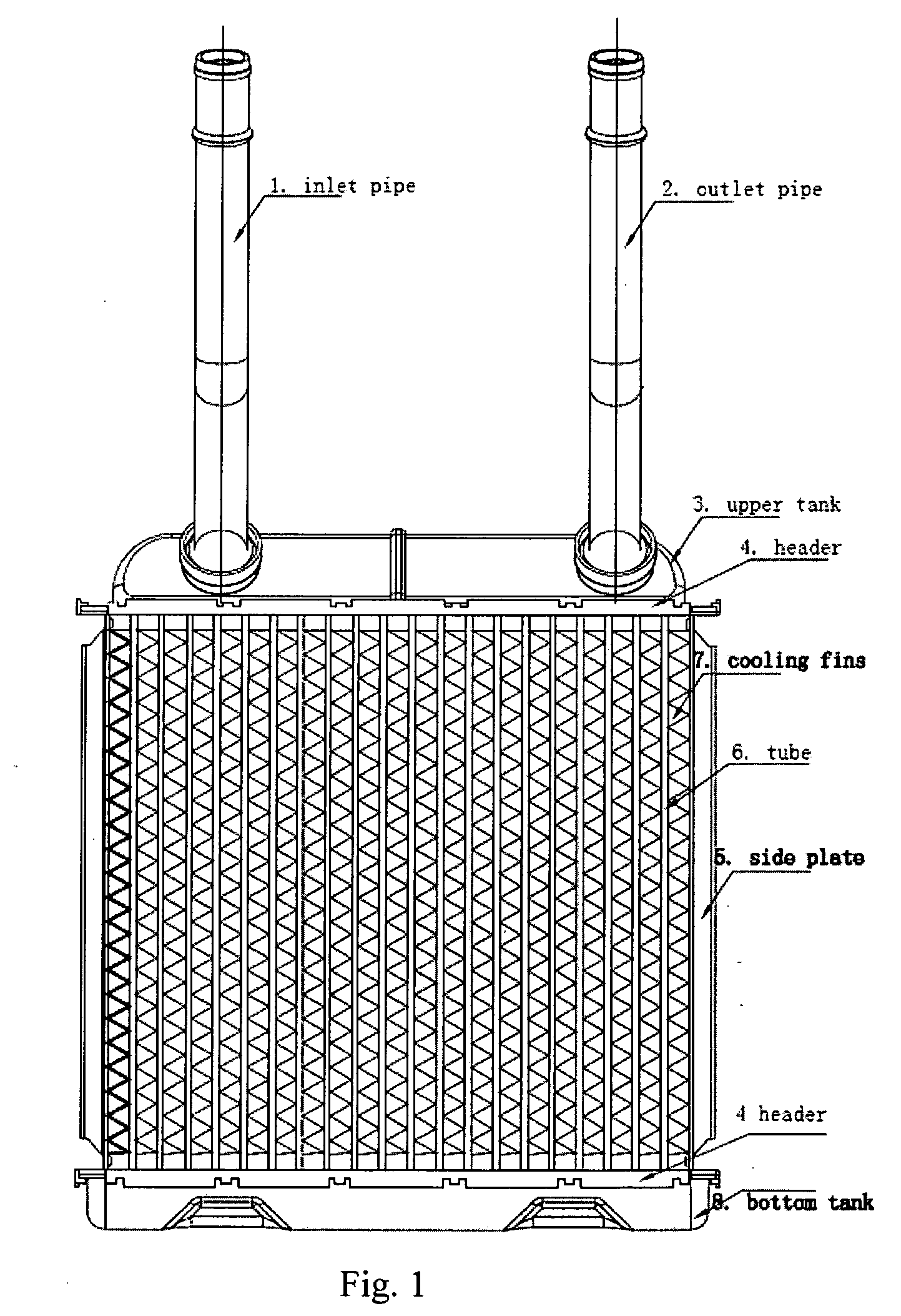
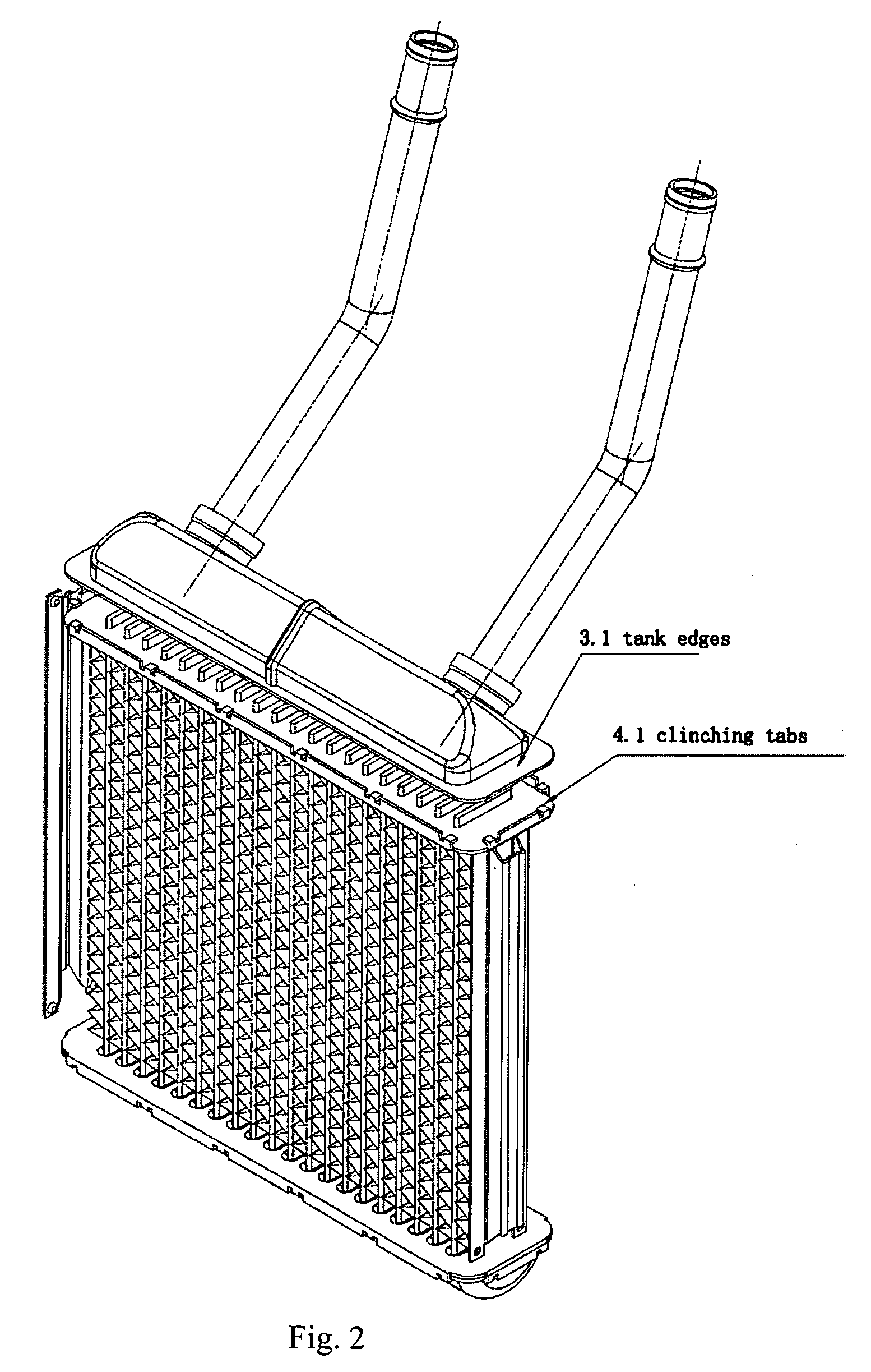
[0030]In reference to FIG. 1, an automotive heater core includes eight parts: inlet pipe 1, outlet pipe 2, upper tank 3, bottom tank 8, header 4, tube 6, cooling fins 7 and side plate 5. Said header (4) has clinching tabs (4.1) around the headers connecting to the upper tank (3) and to the bottom tank (8) as shown in FIG. 2, 3, 4, 5. When assembling said clinching tabs 4.1 are clamped to the edges 3.1 of the upper 3 and bottom tanks 8 for brazing, as shown in FIGS. 6 and 7. This type of clamping can be applied to the connection of header and tank of all heater cores and radiators for heavy duty applications.

[0031]Said side plates (5) have two button protuberances (5.1) or retaining tabs (5.2) at both ends of the side plates (5) where the cooling fins (7) end as shown in FIGS. 8, 9, 10 and 11, 12 (in FIGS. 8, 9, 10 there are 2 button protuberances 5.1 at each end of the side plates, in FIGS. 11, 12 there are 2 retaining tabs 5.2 at each end of the side plates.)

[0032]Said header (4) h...


PUM


Abstract

This invention involves a type of automotive heater core, including upper tank (3), bottom tank (8), inlet pipe (1), outlet pipe (2), header (4), side plate (5), cooling fins (7) and tubes (6), said header (4) has clinching tabs (4.1) around the headers connecting to the upper tank (3) and to the bottom tank (8); said side plates (5) have two button protuberances (5.1) or retaining tabs at both ends of the side plates (5) where the cooling fins (7) end; said header (4) has clinching tabs (4.2) located at the center of the minor dimension of the headers (4) and the center of the ends of the side plates (5). This heater core has firm bonding between tank and header, header and side plate, and is free from the partial melting, burning and dropping of the cooling fins.

Description

CROSS REFERENCE TO RELATED PATENT APPLICATION[0001]This application claims the priority of the Chinese patent application No. 200810018985.5 filed on Jan. 30, 2008, which application is incorporated herein by reference.FIELD OF THE INVENTION[0002]The invention involves an automotive heater core, it belongs to the field of auto parts technology.BACKGROUND OF THE INVENTION[0003]An automotive heater core is a radiator dissipating heat into the car cabin using cooling water from the engine, it includes: inlet pipe, outlet pipe, upper tank, bottom tank, header, tube, cooling fins and side plate. The shortages of old art are:[0004]1. Brazing between the header and tank is not firm, which causes leak and failure of a heater core[0005]2. During the brazing process, as the materials used for cooling fins and header plate are different, they require different temperature of brazing, thus the cooling fins are often melted where they contact the header, which affects negatively the effective co...

Claims


Application Information

Patent Timeline
IPC IPC(8): F28D1/02
CPCF28D1/05366F28F9/001F28F2275/122F28F2275/04F28F9/0224
Inventor XU, HUIXIN
Owner XU HUIXIN
Why Eureka
Try Eureka