
Sensor, sensor unit, and method for producing sensor unit

A sensor unit, sensor element technology, applied in instruments, special recording/indicating devices, equipment with special mechanical means, etc., can solve problems such as damage and interference with sensor measurement performance, and achieve the effect of reducing cost and high signal quality

Active Publication Date: 2014-04-23
ROBERT BOSCH GMBH
View PDF5 Cites 2 Cited by
  • Summary
  • Abstract
  • Description
  • Claims
  • Application Information

AI Technical Summary

Problems solved by technology

The measuring performance of the sensor can be impaired or completely disturbed if interfering values ​​or interfering frequencies, such as vibrations of a drive, occur within the preset frequency range and do not belong to the quantity to be measured

Method used


Image

  • Sensor, sensor unit, and method for producing sensor unit
  • Sensor, sensor unit, and method for producing sensor unit
  • Sensor, sensor unit, and method for producing sensor unit

Examples


Embodiment Construction

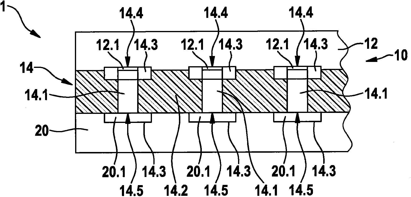
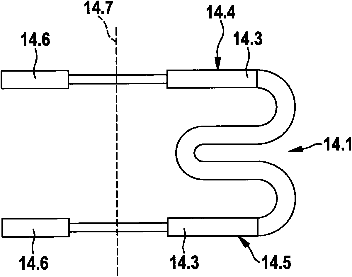
[0027] From Figure 1 to Figure 10 It can be seen that the illustrated exemplary embodiments of sensor units 1 , 1 ′ each comprise a circuit board 20 , 20 ′ and sensors 10 , 10 ′ with sensor elements 12 , 12 ′ for measuring physical quantities.

[0028] According to the invention, the sensor 10 , 10 ′ comprises at least one elastic damping element 14 , 14 ′ which damps external disturbance vibrations or disturbance frequencies and which has an electrical connection for realizing the sensor element 10 , 10 ′. Contacting and / or mechanical contacting means 14.1, 14.1'. Elastic damping elements 14 , 14 ′ are arranged between printed circuit board 20 and sensor element 12 , and together with sensor elements 12 , 12 ′ form sensors 10 , 10 ′ in the exemplary embodiment shown.

[0029] From Figures 1 to 9 It can also be seen that in the first exemplary embodiment the elastic damping element 14 has at least one spring element 14.1 with two contact elements 14.3. All spring elements 1...


PUM


Abstract

The invention relates to a sensor (10) comprising a sensor element (12) for measuring a physical variable. According to the invention, at least one elastic damping element (14) is provided which damps external interfering vibrations and which has means (14.1) for electrically and / or mechanically contacting the sensor element (12).

Description

technical field [0001] The invention relates to a sensor of the type according to independent claim 1, in particular for measuring acceleration or rotational speed, and a corresponding sensor unit of the type according to independent claim 7, and a corresponding sensor unit according to independent claim 8. Types of methods for manufacturing sensor units. Background technique [0002] In modern safety systems, the sensor usually consists of at least one sensor unit for measuring inertial values, for example acceleration and / or rotational speed. Acceleration sensors and / or rotational speed sensors have oscillating masses which operate in a predetermined frequency range. The measuring performance of the sensor may be impaired or completely disturbed if interfering values ​​or interfering frequencies, such as vibrations of the drive, occur within the predetermined frequency range but do not belong to the quantity to be measured. In many applications where a high signal qualit...

Claims


Application Information

Patent Timeline
Patent Type & Authority Applications(China)
IPC IPC(8): G01D3/036
CPCG01P3/14G01D3/036G01P15/0802G01P1/003Y10T29/49128
Inventor M·霍夫泽斯
Owner ROBERT BOSCH GMBH
Learn More