

Binding Structure between Tank and Header of Automotive Heater Core
Inactive Publication Date: 2009-07-30
XU HUIXIN
View PDF3 Cites 2 Cited by
- Summary
- Abstract
- Description
- Claims
- Application Information
AI Technical Summary
Benefits of technology
[0004]The purpose of this invention is to overcome the above shortages, and to provide a kind of structure to strengthen the binding between tank and header of the automotive heater core.
[0006]The clamping of clinching tabs to the edges of the tanks structurally ensures the mechanical strength of the connection between the header to the upper tank and to the bottom tank. It ensures a good brazing and firm bonding between the tanks and the header.
Problems solved by technology
The biggest problem encountered during the manufacturing process is that the brazing between the tank and header is not firm enough thus will cause leak and failure of the heater core.
Method used
View moreImage
Smart ImageViewing Examples

Examples
Embodiment Construction
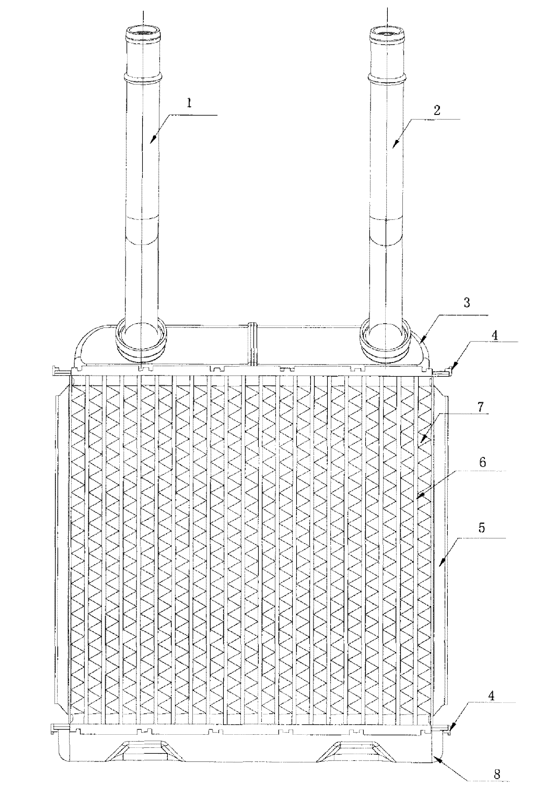
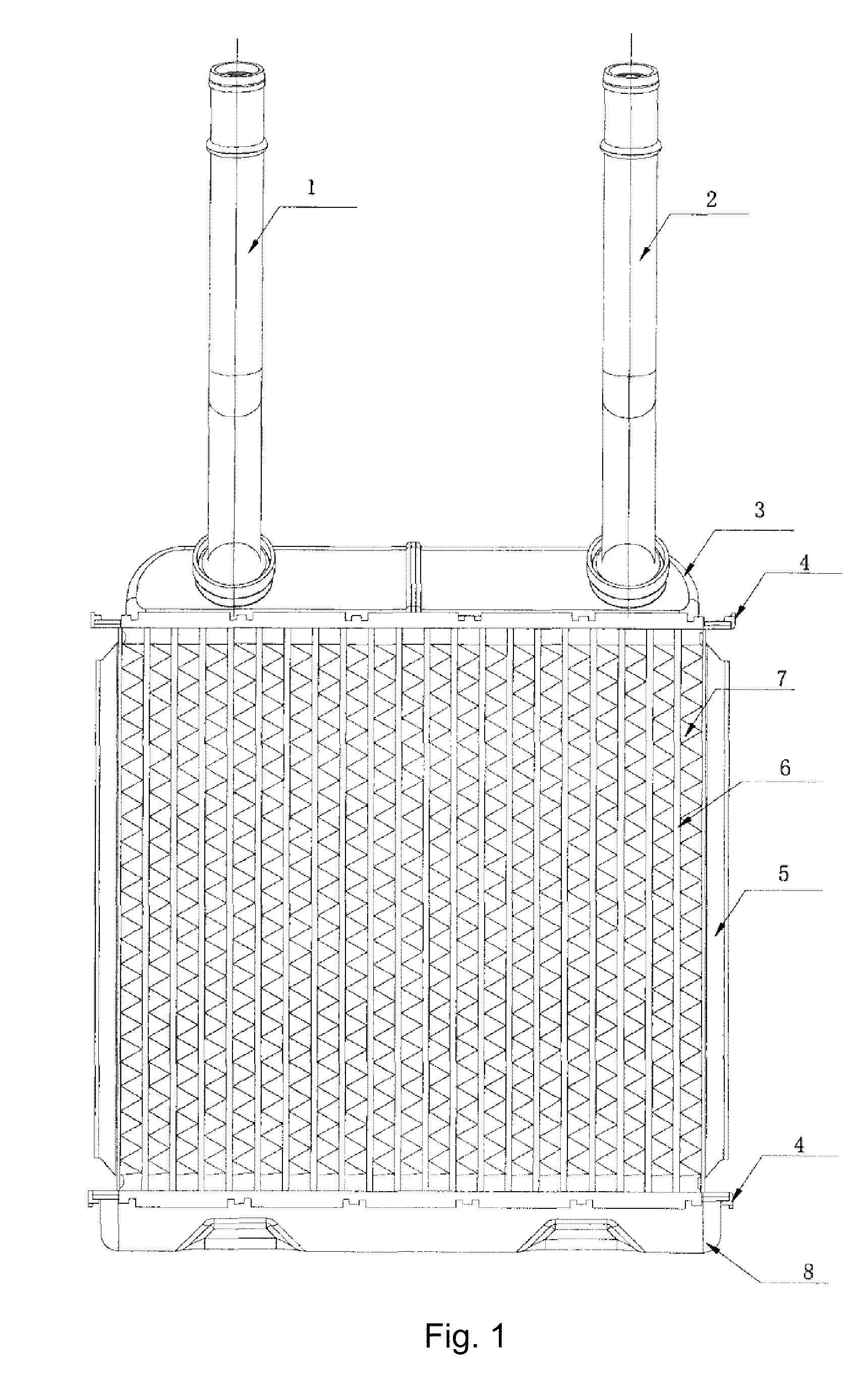
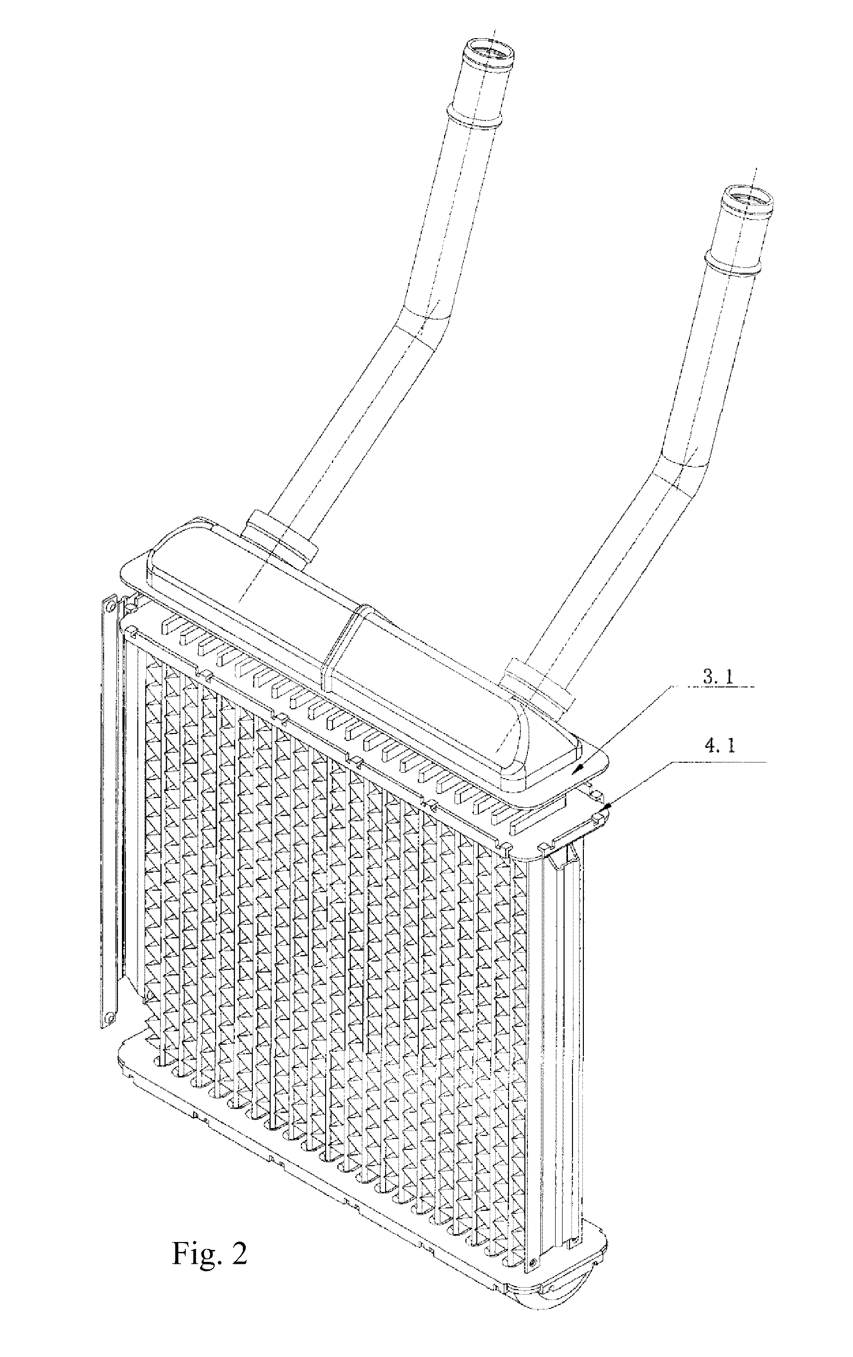
[0010]As shown in FIG. 1, an automotive heater core includes 8 parts: inlet pipe 1, outlet pipe 2, upper tank 3, bottom tank 8, header 4, tube 6, cooling fins 7 and side plate 5. As shown in FIGS. 2, 3, 4, 5 there are some clinching tabs (4.1) around the headers connecting to the upper tank (3) and to the bottom tank (8), when assembled the clinching tabs (4.1) clamp to the edges of the upper tank (3) and the bottom tank (8), then the assembled heater core is brazed as shown in FIGS. 6, 7. This kind of structure can be applied to header and tank's connection in all types of automotive heater cores and industrial radiators.
Login to View More PUM
 Abstract
This invention involves a binding structure between tank and header of an automotive heater core, which belongs to the field of auto parts technology. Said structure includes the upper tank (3), the bottom tank (8) and the header (4). Characteristics of said structure are that there are clinching tabs (4.1) around the headers connecting to the upper tank (3) and to the bottom tank (8). Said clinching tabs (4.1) clamp to the edges of the upper tank (3) and the bottom tank (8). The clamping of clinching tabs to the edges of the tanks structurally ensures the mechanical strength of the binding between the header to the upper tank and to the bottom tank. It ensures a good brazing and firm binding between the tanks and the header.
Description
CROSS REFERENCE TO THE RELATED PATENT APPLICATION[0001]This application claims the priority of the Chinese patent application No. 200810018987.4 filed on Jan. 30, 2008, which application is incorporated herein by reference.FIELD OF THE INVENTION[0002]This invention is applied to an automotive heater core. It is a binding structure between tank and header of automotive heater core. It belongs to the field of auto parts technology.BACKGROUND OF THE INVENTION[0003]An automotive heater core is a radiator dissipating heat into the car cabin using cooling water from the engine, it includes: inlet pipe, outlet pipe, upper tank, bottom tank, header, tube, cooling fins and side plate. The technique used for manufacturing heater core is brazing. The biggest problem encountered during the manufacturing process is that the brazing between the tank and header is not firm enough thus will cause leak and failure of the heater core.SUMMARY OF THE INVENTION[0004]The purpose of this invention is to o...
Claims
Login to View More Application Information
Patent Timeline
 IPC IPC(8): F28F9/02
CPCF28F9/0224F28F2275/122F28F2275/04
InventorXU, HUIXIN
OwnerXU HUIXIN