Manufacturing method of impeller for fluid transmitting device

a technology of fluid transmission device and manufacturing method, which is applied in the direction of fluid gearings, metal rolling stands, liquid fuel engine components, etc., can solve the problems of reducing and distributing the core strictly horizontally. , to achieve the effect of improving the yield of brazing material

Active Publication Date: 2014-11-11
YUTAKA GIKEN CO LTD
View PDF11 Cites 2 Cited by
  • Summary
  • Abstract
  • Description
  • Claims
  • Application Information

AI Technical Summary

Benefits of technology

[0006]The present invention has been made in view of such a circumstance and has an object to provide a manufacturing method of an impeller for a fluid transmitting device by which in a step of causing a molten brazing material to penetrate into gaps between coupling pieces and positioning holes that are fitted to each other and further into gaps between a core and blades, the molten brazing material can be efficiently guided to the gaps between the coupling pieces and positioning holes that are fitted to each other, to thereby improve the yield of the brazing material and also to prevent an influence of a residual brazing material over the rotational balance of the impeller.
[0008]According to the first aspect of the present invention, in the third step, the molten brazing material is guided to the positioning holes through the multiple guide grooves previously provided in the inner surface of the core and aligned in the peripheral direction. Therefore, even when the brazing material is disposed somewhat off the guide grooves in the second step, the brazing material, after melting, flows into the guide grooves and then is guided and distributed efficiently to all the positioning holes in the third step. As a result, by capillary action, the molten brazing material penetrates into all the gaps between the positioning holes and the coupling pieces, and further flows down and penetrates into the gaps between the mating surfaces of the core and the blades, thus contributing to the brazing at each spot in an efficient way. Accordingly, almost no brazing material remains in the guide grooves, allowing not only an improvement in the yield of the brazing material but also prevention of an influence of a residual brazing material over the rotational balance of the impeller.
[0010]According to the second aspect of the present invention, the guide grooves are capable of smoothly guiding and distributing the molten brazing material to the positioning holes. Moreover, these multiple guide grooves can be formed easily by pressing or cutting.
[0012]According to the third aspect of the present invention, it is possible to effectively prevent the molten brazing material from remaining in the guide grooves.
[0014]According to the fourth aspect of the present invention, the multiple guide grooves can be all press-molded collectively in the inner surface of the core. Moreover, since the inner surface of each press-molded guide groove is smooth, the guiding of the brazing material through the guide groove to its corresponding positioning holes is smooth. Such smooth guidance is effective in preventing the molten brazing material from remaining in the guide groove.
[0016]According to the fifth aspect of the present invention, each of the guide grooves includes multiple grooves arranged in parallel and allowing communication between the adjacent positioning holes. The groove depth of each of the multiple guide grooves arranged in parallel is set sufficiently smaller than the groove depth in the case where the adjacent positioning holes communicate with each other through a single guide groove, and the molten brazing material is efficiently collected in a larger area and can be guided to the positioning holes. Accordingly, deformation of the impeller due to the formation of the guide grooves can be prevented more securely. This configuration is particularly effective in a case where the portion of the inner surface of the core which appears as a bottom portion when the core is disposed horizontally is relatively flat.

Problems solved by technology

Specifically, in the third step in which the molten brazing material is caused to penetrate into the gaps between the coupling pieces and positioning holes that are fitted to each other and further into the gaps between the core and the blades, the molten brazing material may flow somewhat unevenly on one side, in the radial direction, of the core since it is difficult to dispose the core strictly horizontally.
Such unnecessary adhesion may lower the yield of the brazing material and further impair the rotational balance of the impeller in some cases.

Method used


Image

  • Manufacturing method of impeller for fluid transmitting device
  • Manufacturing method of impeller for fluid transmitting device
  • Manufacturing method of impeller for fluid transmitting device

Examples


first embodiment

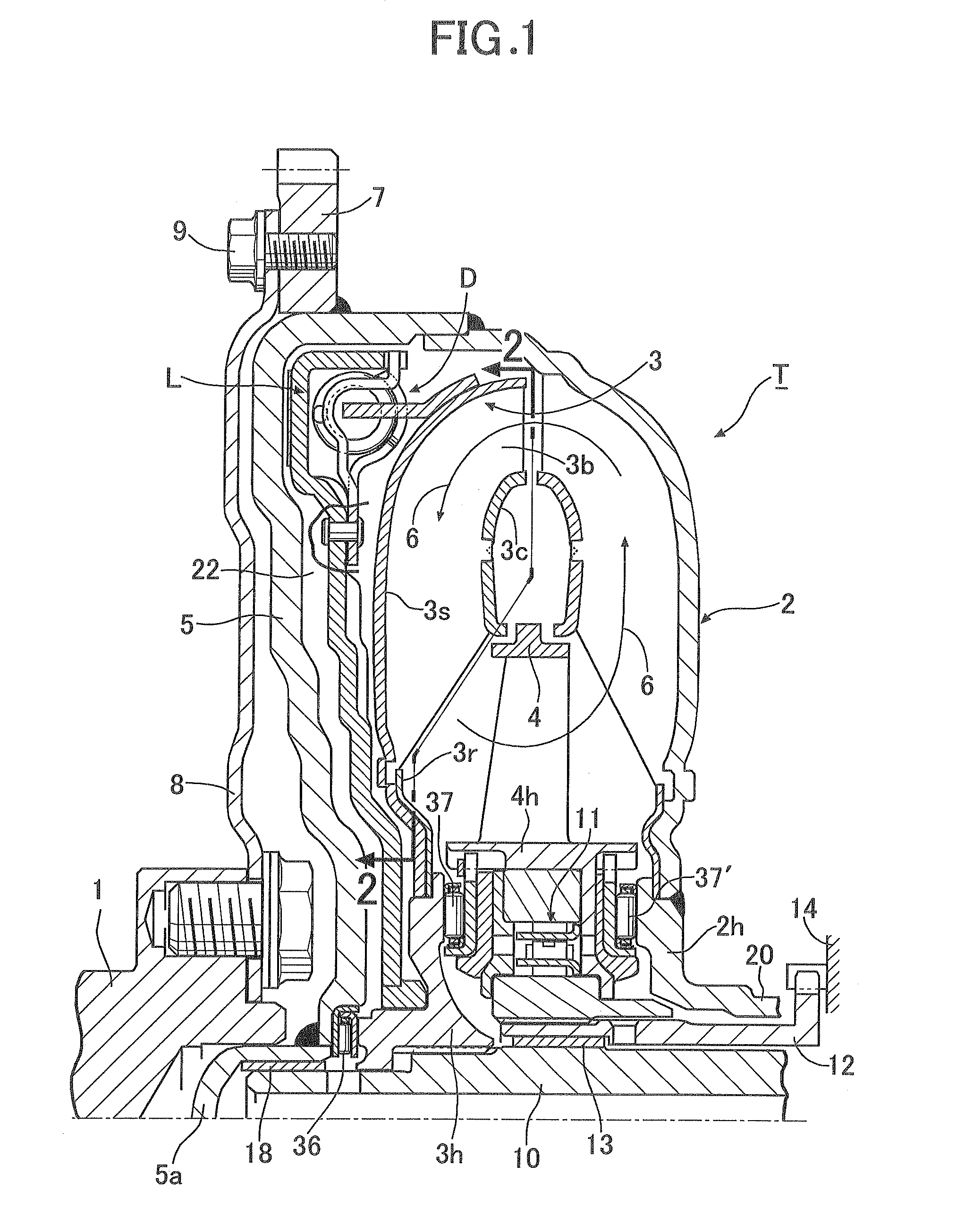
[0026]First of all, the present invention shown in FIGS. 1 to 5C will be described. In FIG. 1, a torque converter T as a fluid transmitting device includes a pump impeller 2, a turbine impeller 3 disposed facing the pump impeller 2, and a stator impeller 4 disposed between inner peripheral portions of the pump impeller 2 and turbine impeller 3. These three impellers 2, 3, and 4 define therebetween a circulation circuit 6 through which to transmit power by means of hydraulic oil.

[0027]A side cover 5 covering the outer surface of the turbine impeller 3 is provided consecutively and integrally by welding to an outer peripheral portion of a shell 2s of the pump impeller 2. A ring gear 7 for starting an engine is welded to the outer peripheral surface of the side cover 5, and a drive plate 8 joined to a crankshaft 1 of the engine is fixed to this ring gear 7 with a bolt 9. A thrust needle bearing 36 is interposed between a hub 3h of the turbine impeller 3 and the side cover 5.

[0028]An ou...

second embodiment

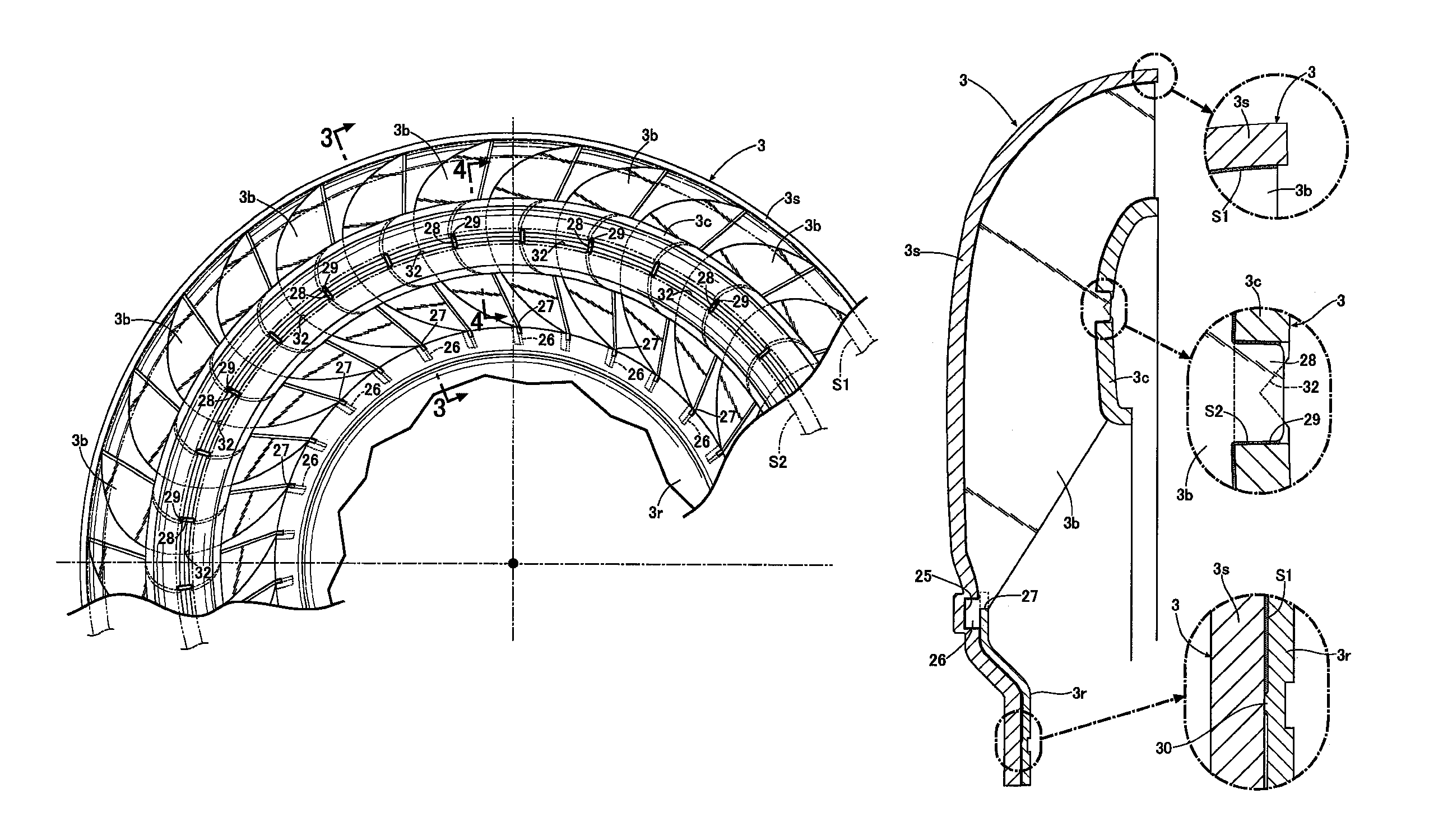
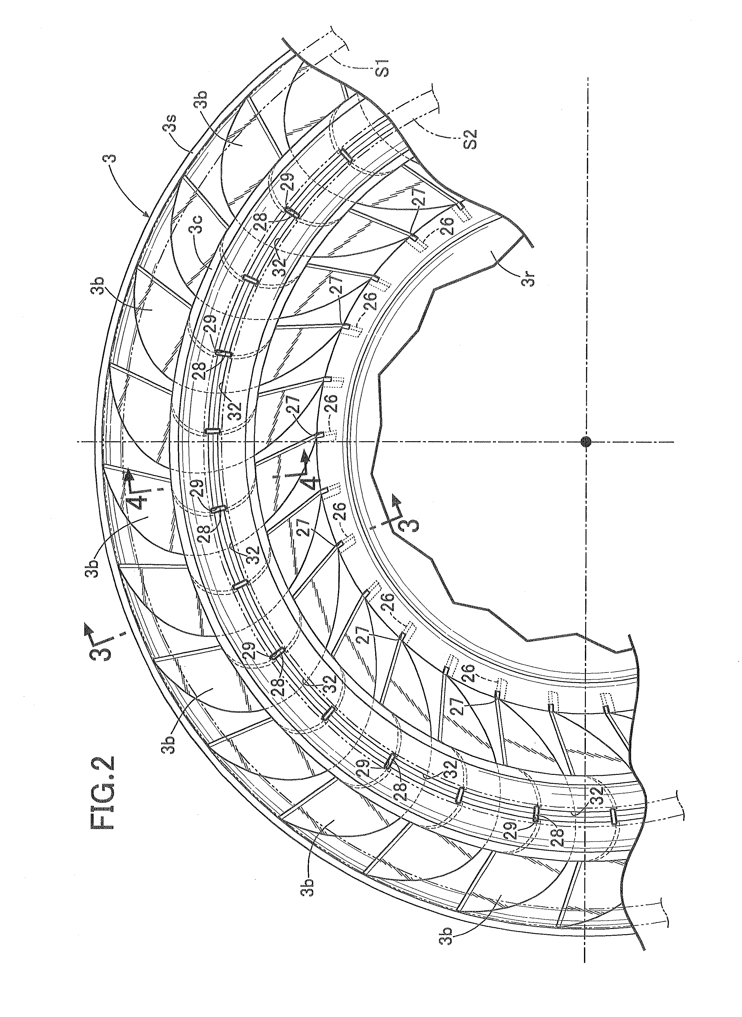
[0053]Next, the present invention shown in FIGS. 6 and 7 will be described.

[0054]In the second embodiment, the adjacent positioning holes 29 communicate with each other through multiple guide grooves 32 that are arranged in parallel. In this configuration, the groove depth of each of the multiple guide grooves 32 is set smaller than the groove depth of each guide groove 32 in the previous embodiment. The other features of the configuration are the same as the previous embodiment. Thus, in FIGS. 6 and 7, the portions corresponding to those in the previous embodiment are denoted by the same reference numerals, and overlapping descriptions are omitted.

[0055]According to the second embodiment, the groove depth of each of the multiple guide grooves 32 arranged in parallel is set sufficiently smaller than the groove depth in the previous embodiment in which the adjacent positioning holes 29 communicate with each other through a single guide groove 32, and the molten brazing material is ef...


PUM

PropertyMeasurementUnit
thicknessaaaaaaaaaa
thicknessaaaaaaaaaa
groove depthaaaaaaaaaa

Abstract

In a manufacturing method of an impeller for a fluid transmitting device, multiple guide grooves aligned in a peripheral direction to allow communication between adjacent ones of multiple positioning holes are provided in a concave inner surface of a core in advance; and in a step of melting a brazing material and causing the molten brazing material to penetrate into gaps between coupling pieces and positioning holes that are fitted to each other and further into gaps between the core and the blades, the molten brazing material is guided to the positioning holes through the multiple guide grooves. Accordingly, the step allows the molten brazing material to be efficiently guided to the gaps between the coupling pieces and positioning holes, thereby improving the yield of the brazing material and preventing an influence of a residual brazing material over the rotational balance of the impeller.

Description

BACKGROUND OF THE INVENTION[0001]1. Field of the Invention[0002]The present invention relates to a manufacturing method of an impeller for a fluid transmitting device such as a torque converter or a fluid coupling used in a vehicle or an industrial machine. The present invention relates particularly to an improvement in a manufacturing method of an impeller for a fluid transmitting device, the impeller including an annular, bowl-shaped shell, multiple blades joined to an inner surface of the shell and arranged in a peripheral direction of the shell, and a core having an outer peripheral surface brazed to an intermediate portion of each of the blades so as to couple the intermediate portions of the blades to each other.[0003]2. Description of the Related Art[0004]As described in Japanese Patent Application Laid-open No. 2008-82409, a method has conventionally been known in which the following four steps are performed in the manufacturing of an impeller for such a fluid transmitting d...

Claims


Application Information

Patent Timeline
Patent Type & Authority Patents(United States)
IPC IPC(8): B21D53/78F16H41/28
CPCF16H41/28Y10T29/49321Y10T29/49316Y10T29/49993
Inventor NANBARA, MASARUMASUDA, TETSUYA
Owner YUTAKA GIKEN CO LTD
Why Eureka
Try Eureka