
Cable bed and cable laying method

a cable bed and cable laying technology, applied in the direction of cable laying apparatus, machine supports, other domestic objects, etc., can solve the problems of excessive burden, heavy and long cable or pipe to be drawn onto the (ladder-like) cable bed, and considerable friction with the cable bed or its rungs

Inactive Publication Date: 2000-02-01
MIRAI KOGYO KK
View PDF3 Cites 37 Cited by
  • Summary
  • Abstract
  • Description
  • Claims
  • Application Information

AI Technical Summary

Problems solved by technology

In general, a cable or pipe to be drawn onto a (ladder-like) cable bed is heavy and long, and generates (during a cable laying or drawing operation) considerable friction with the cable bed or its rungs.
However, in such an arrangement, the roller rungs 10, relatively fewer in number, are destined to shoulder all weight of the cable W laid on the cable bed 1, which will be too much a burden for such fragile conventional roller rungs 10.
In addition, such an arrangement is impractical conventionally, for it is such support rungs 3 that are to support cable weight.
It is impractical either to provide a cable bed 1 with conventional roller rungs 10 alone, for it is required to incorporate too many roller rungs 10, which will be much more costly than utilizing support rungs 3.

Method used


Image

  • Cable bed and cable laying method
  • Cable bed and cable laying method
  • Cable bed and cable laying method

Examples


Embodiment Construction

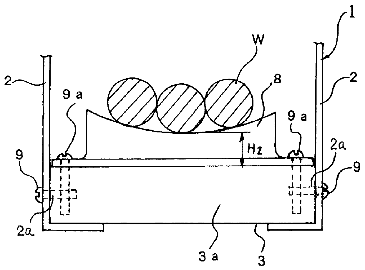
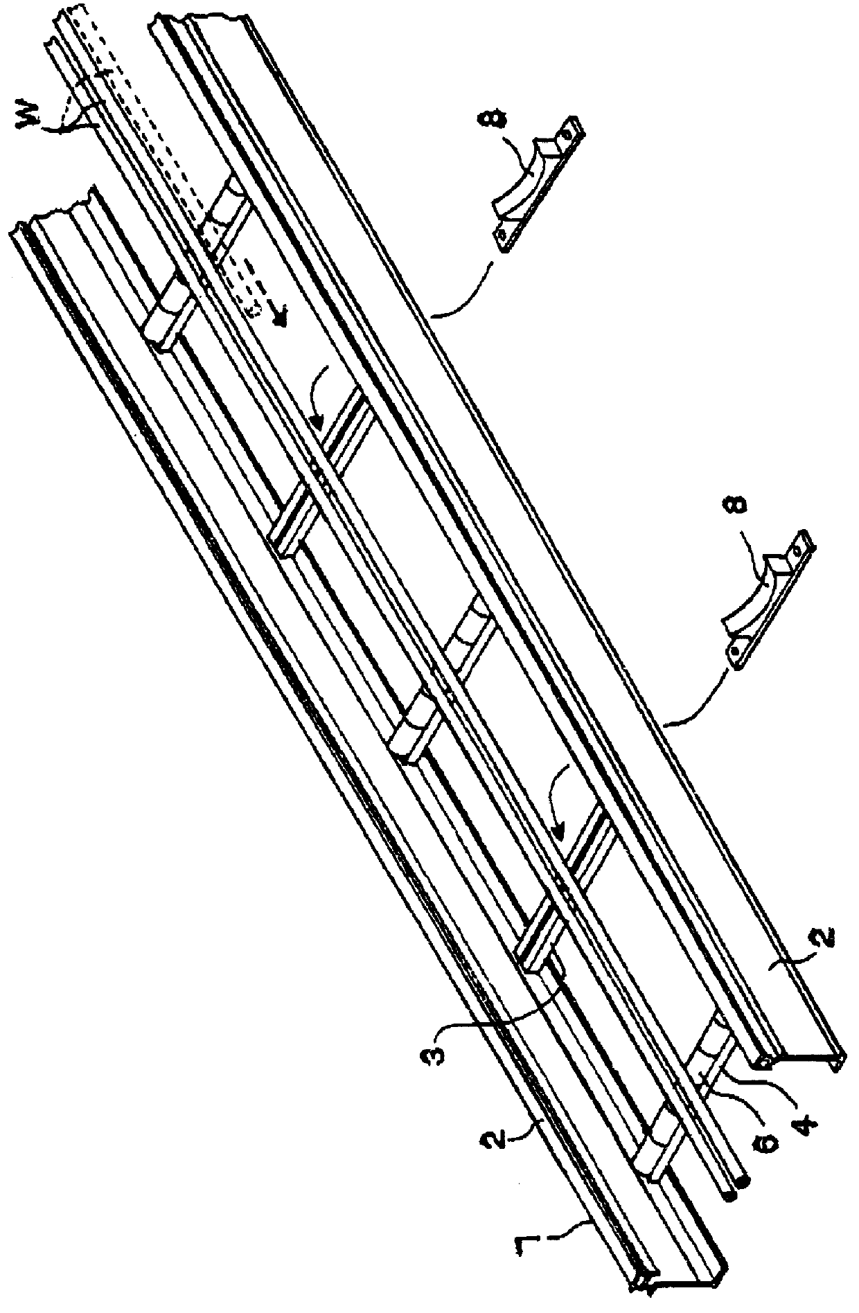
In FIGS. 1 to 3A, a cable bed 1 according to an embodiment of the present invention is shown, comprising a pair of L-shaped side rails 2 running in parallel, a plurality of support rungs 3 mounted across the side rails 2 at appropriate intervals, and a plurality of roller rungs 4 mounted across the side rails 2 at appropriate intervals among the support rungs 3. An arrangement of roller rungs 4 and support rungs 3 along the side rails 2 is shown in FIG. 3. Other arrangements of roller rungs 4 and support rungs 3, such as a repetition of a unit consisting of two support rungs and one roller rung or one support rung and two roller rungs, are possible.

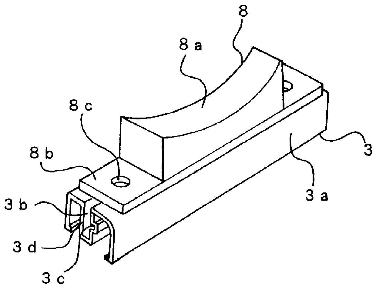
In FIG. 1, each support rung 3 has a support block 8 thereon, on which are laid three cables W. The support blocks 8 are to be attached on the support rungs 3 by means of threaded bolts 9a after a cable or cables W are initially laid over the support rungs 3.

The side rails 2 is advantageously made of aluminum, however, other appropriate m...


PUM


Abstract

A roller-support rung arrangement for a cable bed and a cable laying method utilizing the arrangement are disclosed. The cable bed has roller rungs and support rungs on which support blocks are to be mounted. Generally, the roller rungs are mounted on the side rails at a higher level than the support rungs so that a cable drawn onto the cable bed initially contacts only the roller rungs for easy drawing of the cable. Generally, the support blocks are provided on the support rungs after the cable is initially laid on the cable bed such that the support blocks can substantially support the cable weight.

Description

1. Field of the InventionThis invention generally relates to a ladder-type cable bed. This invention more particularly relates to a ladder-type cable bed incorporating roller rungs, which utilizes cable support blocks to be mounted on support rungs after an initial cable laying operation. This invention also relates to a cable laying method using such a cable bed.2. Prior ArtJapanese Laid-Open Utility Model Publication 62-172210 discloses a ladder-type cable bed 1 incorporating & plurality of roller rungs 10 as shown in FIGS. 12 and 13, FIG. 12 being a partial perspective view and FIG. 13 being a partial front view with a longitudinally extending side wall 2 sectioned.Each roller rung 10 comprises a plurality of disk rollers 12 turnably mounted on an axial shaft 11 which has a projection 11a (with a threaded hole) on each end thereof. Each projection 11a is fixedly connected to a corresponding side wall 2 with a threaded bolt 6 screwed through a hole provided on the side wall 2 from...

Claims


Application Information

Patent Timeline
IPC IPC(8): H02G1/06
CPCH02G1/06
Inventor SHIMIZU, SHOHACHI
Owner MIRAI KOGYO KK
Features
  • Generate Ideas
  • Intellectual Property
  • Life Sciences
  • Materials
  • Tech Scout
  • Unparalleled Data Quality
  • Higher Quality Content
  • 60% Fewer Hallucinations
Learn More