Side-knock type mechanical pencil

a mechanical pencil and side-knock technology, applied in the direction of propelling pencils, ink reservoir pens, printing, etc., can solve the problems of insufficient forward or forward feeding, failure to feed in a sufficient amount, and reducing the cost of products

Inactive Publication Date: 2000-05-23
PENTEL KK
View PDF8 Cites 38 Cited by
  • Summary
  • Abstract
  • Description
  • Claims
  • Application Information

AI Technical Summary

Problems solved by technology

At this time, a failure occurs in the feeding of the lead, i.e., the lead is caught by the bending so that it becomes unable to be fed in the forward direction or in a sufficient amount.
It has increasingly necessary to decrease the costs of products because of higher labor costs.
However, the formation of two parts as one integ...

Method used


Image

  • Side-knock type mechanical pencil
  • Side-knock type mechanical pencil
  • Side-knock type mechanical pencil

Examples


first embodiment

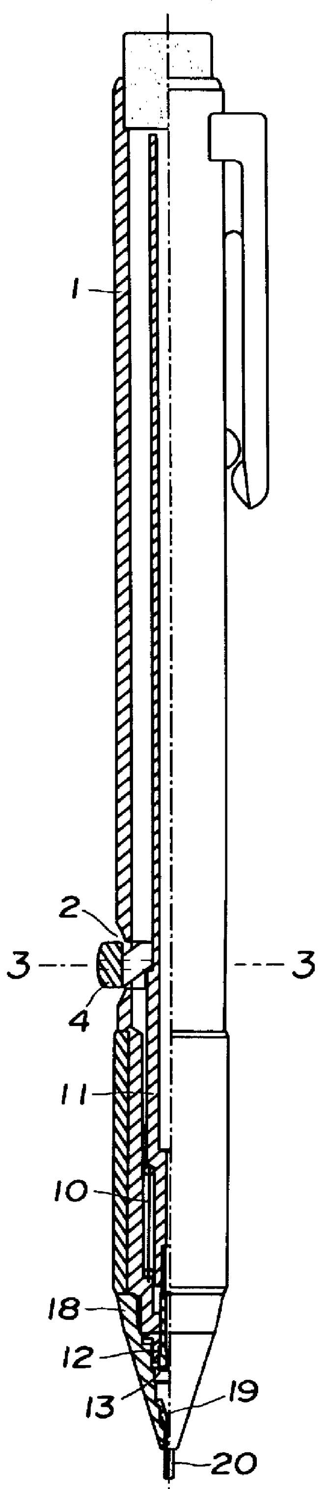
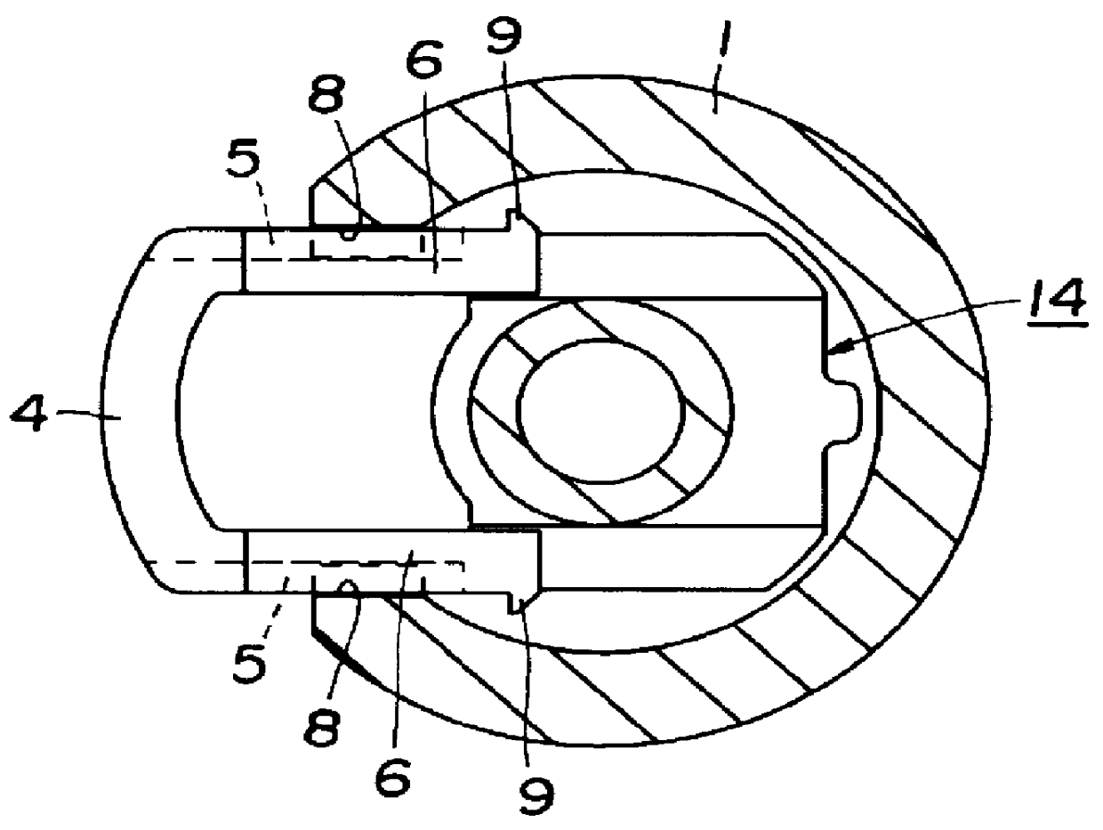
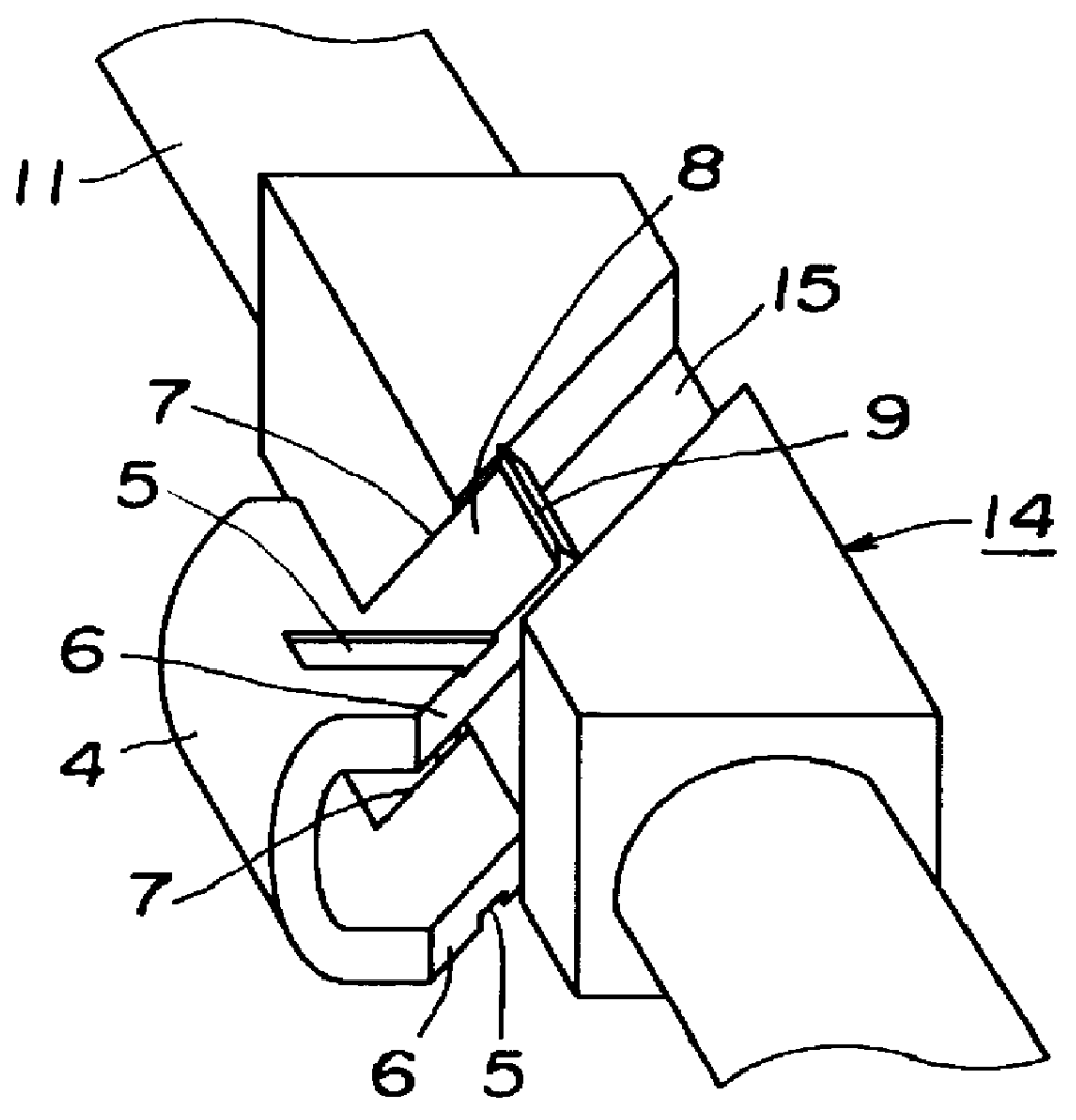
FIGS. 1 to 6 are explanatory views showing a A through-hole 2 is formed in the side portion of a barrel 1, and guide projections 3 are formed in the through-hole 2. A knock button 4 having a U-shaped cross section is fitted through the through-hole 2 in such a manner as to be movable in opposite radial directions perpendicular to the barrel 1. Guide grooves 5 which are slideably engaged with the respective guide projections 3 are formed in the opposite external sides of the knock button 4. The knock button 4 also has inclined faces 6 for moving forward a lead feeding mechanism which will be described later. Inclined faces 7 which are parallel to the respective inclined faces 6 are formed on sides opposite to the inclined faces 6. In addition, engagement claws 9 for preventing the knock button 4 from coming off the barrel 1 are respectively formed at the ends of press surfaces 8 of the knock button 4.

A lead tank 11 for storing leads and which is urged rearward by a resilient member ...

second embodiment

FIGS. 10 to 12 are explanatory views showing a The through-hole 2 is formed in the side portion of the barrel 1, and a knock button 28 having a U-shaped cross section is fitted through the through-hole 2 in such a manner as to be movable in opposite radial directions perpendicular to the barrel 1. Cutouts 30 are respectively formed in the intermediate portions of side portions 29 of the knock button 28, and front inclined faces 31 are formed at the front ends of the respective side portions 29 of the knock button 28. The side portions of the knock button 28 each of which is defined by either one of the cutouts 30 and the corresponding one of the front inclined faces 31 constitute first engagement portions 32, respectively. Rear inclined faces 33 are respectively formed on the rear sides of the cutouts 30. The side portions of the knock button 28, each of which is defined by either one of the rear inclined faces 33 and the corresponding one of rear end faces 34 of the knock button 2...

third embodiment

A third embodiment will be described below with reference to FIGS. 16 and 17. In the third embodiment, to prevent shaking of the knock button, an improvement is introduced into the state of the knock button fitted through the through-hole in each of the first and second embodiments. In the following description, identical reference numerals are used to denote constituent elements identical to those used in the second embodiment. The knock button 28 is formed to increase in width toward its lower portion (toward the engagement claws 36), as viewed in cross section, so that the lower portion of the knock button 28 is press-fitted through the through-hole 2. This large-width portion constitutes a press-fitting portion 54. In addition, the knock button 28 is formed to decrease in width toward its upper portion, so that the width of the upper portion is smaller than that of the through-hole 2. This small-width portion constitutes a non-press-fitting portion 55. If the knock button 28 is ...


PUM


Abstract

PCT No. PCT/JP96/00139 Sec. 371 Date Jul. 29, 1997 Sec. 102(e) Date Jul. 29, 1997 PCT Filed Jan. 26, 1996 PCT Pub. No. WO96/23666 PCT Pub. Date Aug. 8, 1996A side-knock type mechanical pencil comprises a barrel having a front end, a rear end a lead feeding mechanism disposed in the barrel for axial movement within the barrel to feed a pencil lead toward the front end of the barrel. A knock button is disposed in a side portion of the barrel so that the knock button can be pressed inward in a radial direction of the barrel to move the lead feeding mechanism axially within the barrel to thereby feed the pencil lead toward the front end of the barrel. A lead passageway is disposed in the barrel for passing therethrough the pencil lead in a direction toward the front end of the barrel. The lead passageway has a diameter at least twice as large as a diameter of the pencil lead. At least one lead receiving member is disposed in the barrel between the lead passageway and the knock button for receiving the pencil lead. The lead receiving member has a lead insertion hole for permitting the pencil lead to pass therethrough and a head portion having an external diameter approximately equal to an internal diameter of the barrel.

Description

1. Field of the InventionThe present invention relates to a side-knock type mechanical pencil in which a lead feeding mechanism is disposed in an inside portion of a barrel and a knock button is disposed in a side portion of the barrel so that the knock button can be pressed inward in a radial direction of the barrel, and the knock button is pressed to move the lead feeding mechanism back and forth, thereby feeding a lead from the barrel.2. Background ArtJapanese Utility Model Laid-Open No. 55-171577 / 1980 is known as one example of a side-knock type mechanical pencil. This publication describes a head and a side-knock type mechanical pencil in which an internal tube provided with a mouth ring at its lower end and shorter than an external barrel is movably accommodated in the external barrel; an internal mechanism return spring and engaging means for projecting the mouth ring from the lower end of the external barrel and retracting the mouth ring into the external barrel are provided...

Claims


Application Information

Patent Timeline
IPC IPC(8): B43K21/16B43K24/08B43K21/00B43K24/00
CPCB43K24/082B43K21/16
Inventor MARUYAMA, SHIGEKIONUKI, SOUJI
Owner PENTEL KK
Why Eureka
Try Eureka