Disk driving device with small centering force variation

a technology of centering force variation and driving device, which is applied in the direction of magnetic recording, data recording, instruments, etc., can solve the problems of reducing the centering precision of the disk, causing more breakage of the disk d, and causing read errors to occur

Inactive Publication Date: 2000-08-22
ALPS ALPINE CO LTD
View PDF10 Cites 15 Cited by
  • Summary
  • Abstract
  • Description
  • Claims
  • Application Information

AI Technical Summary

Problems solved by technology

When a load is repeatedly exerted onto each fulcrum 16b as a result of loading and unloading the disk, fatigue of the fulcrum 16b results, causing the disk D to break more often.
Therefore, large variations result in the disk centering forces produced at the tapering portions due to dimensional var

Method used


Image

  • Disk driving device with small centering force variation
  • Disk driving device with small centering force variation
  • Disk driving device with small centering force variation

Examples


Embodiment Construction

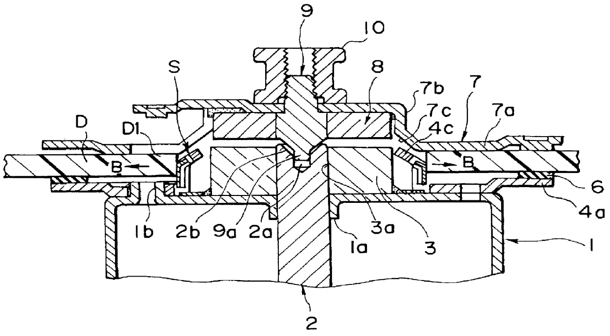
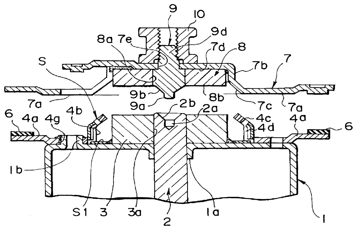
A description will now be given of preferred embodiments of a disk driving device of the present invention, with reference to FIGS. 1 to 8. The disk driving device in FIG. 1 comprises a rotor yoke 1 composed of an iron plate or the like that is rotationally driven using a drive coil of a spindle motor (not shown). The rotor yoke 1 includes a boss hole 1a and a plurality of protrusions 1b. The boss hole 1a is formed in the center of the yoke 1 by burring or the like so as to extend downward. The plurality of protrusions 1b are formed at the upper surface of the yoke 1 towards the outer peripheral side so as to protrude upwards. A rotary shaft 2 is press-fitted and affixed to the boss hole 1a.

The rotary shaft 2 has one end thereof extending upward from the upper surface of the rotor yoke 1. A cylindrical alignment hole 2a is formed in the rotational center of this end, and a chamfered portion 2b is formed therearound.

At the upper center portion of the rotor yoke 1 is disposed a disk-s...


PUM


Abstract

A disk driving device including a centering member mounted to an inner portion of a cylindrical portion of a turntable. The centering member includes a linking portion serving as fulcra and a centering portion separated from the linking portion. The centering portion is resiliently biased with an outward force that acts parallel to a flange providing a disk-mounting surface of the turntable in order to center a disk.

Description

1. Field of the InventionThe present invention relates to a disk driving device for driving a disk such as a compact disk or a CD-ROM.2. Description of the Related ArtA description will be given of a conventional disk driving device of the above type, with reference to FIGS. 10 to 13.In the conventional disk driving device in the figures, a spindle motor (not shown) causes rotation of a rotor yoke 11, which causes rotation of a turntable 13 having mounted thereto a rotary shaft 12 by press-fitting or the like. The turntable 13 is made of brass that is subjected to turning or the like. A cylindrical portion 13a is formed around the center portion of the turntable 13, with the aforementioned rotary shaft 12 press-fitted and secured to the center of the cylindrical portion 13a. A disk-shaped flange 13b is formed at the outer peripheral side of the cylindrical portion 13a, and has a flat surface having affixed thereto with an adhesive tape an anti-slipping sheet 14 serving as the disk-m...

Claims


Application Information

Patent Timeline
IPC IPC(8): G11B19/20G11B17/028
CPCG11B17/0282G11B17/0284G11B19/2009G11B19/20
Inventor IWANAGA, ATSUSHI
Owner ALPS ALPINE CO LTD
Why Eureka
Try Eureka