Mortise latch vertical rod exit device

a technology of mortise latch and exit device, which is applied in the direction of fastening means, mechanical devices, carpet fasteners, etc., can solve the problems of obstructing wheelchairs and carts, and affecting the use of doors

Inactive Publication Date: 2000-09-19
SARGENT MANUFACTURING CO INC
View PDF33 Cites 46 Cited by
  • Summary
  • Abstract
  • Description
  • Claims
  • Application Information

AI Technical Summary

Problems solved by technology

Conventional vertical rod exit devices, however, suffer from numerous problems.
One problem with this design is that the downwardly extending rod, when surface mounted on the door, will interfere with the use of the door.
The lower rod tends to catch and obstruct wheelchairs and carts passing through the door, particularly when the door is provided with an automatic closure device that continuously urges the door towards the closed position.
Although vertical rod designs are known in which the rods are mounted inside the door, such solutions are expensive and not easily retrofitted to existing doors.
Another difficulty with the lower vertical rod is that the bottom latch must engage a strike plate in the floor.
The floor mounted strike plate poses a tripping hazard which is a liability concern.
Removal of the lower rod, however, compromises the security of the door as the door is now latched only by the upper latch.
While this arrangement...

Method used


Image

  • Mortise latch vertical rod exit device
  • Mortise latch vertical rod exit device
  • Mortise latch vertical rod exit device

Examples


Embodiment Construction

)

In describing the preferred embodiment of the present invention, reference will be made herein to FIGS. 1-7 of the drawings in which like numerals refer to like features of the invention.

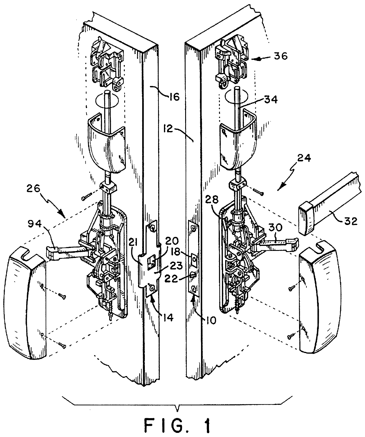
FIG. 1 shows the preferred embodiment of the present invention installed in a double door configuration. The invention includes an active mortise latch mechanism 10 installed in an active door 12 and a passive mortise latch mechanism 14 installed in a passive door 16. The active mortise mechanism includes a latch bolt 18 (shown retracted) which engages an opening 20 in the passive mortise latch mechanism when the doors are closed and aligned. Although the doors are referred to here as the "active" door and the "passive door", as will be clear from the description below, these terms are used for convenience only. Both doors may be freely opened or closed without regard to the open or closed position of the other door.

An activation bolt 22, shown in the extended position in FIG. 1, is pushed back int...


PUM


Abstract

A mortise latch and vertical rod exit device latches at a center point between two doors and at top points between each door and the door frame. Optionally vertical rods may also be used to latch at bottom points between the doors and the floor. The latch includes an active and a passive latch mechanism operated by corresponding operating mechanisms. The mortise latch mechanisms cooperatively interact so that either door may be opened first, and either door may be closed first, without regard to the position of the other door. The active mortise latch mechanism includes a latch bolt and an activation bolt arranged so that one bolt is retracted when the other is extended, except when the doors are being opened or closed, when both bolts are retracted. The active mortise latch mechanism automatically retracts the latch bolt when the doors are not aligned and automatically extends the latch bolt when the doors are aligned. The passive mortise latch mechanism ejects the latch bolt as needed to allow the passive door to be opened first.

Description

1. Field of the InventionThis invention relates to exit devices using latch mechanisms mortised into the door, particularly mortise latch mechanisms used in combination with vertical rod latch assemblies. More specifically, this invention relates to mortise latch mechanisms suitable for use in both single and double door installations.2. Description of Related ArtExit devices using vertical rod mechanisms to latch the door at the top and bottom are widely used in public buildings, particularly where provision must be made for rapid operation in an emergency to evacuate the building. Such devices usually employ a push rail, a push bar, an emergency push plate or a similar type of opening mechanism that operates with inward pressure. This allows the exit device to open quickly and reliably under the pressure of a large number of people trying to exit the building in an emergency.Vertical rod exit devices are often used on double door installations where both doors can be opened to pro...

Claims


Application Information

Patent Timeline
IPC IPC(8): E05B65/10E05C7/06E05C7/00
CPCE05B65/1046E05B65/1006E05C7/06Y10S292/21Y10T292/0971
Inventor PICARD, DANIEL J.ELLER, DARREN C.
Owner SARGENT MANUFACTURING CO INC
Why Eureka
Try Eureka