Backrest structure of a chair, particularly a drum chair

a backrest structure and drum chair technology, applied in the field of drum chair backrest structure, can solve the problems of chair tending to move and threaten to fall, chair compactness, and the need for extra dismantling of the fixed screw f2

Inactive Publication Date: 2001-02-27
HOSHINO GAKKI COMPANY LIMITED
View PDF3 Cites 14 Cited by
  • Summary
  • Abstract
  • Description
  • Claims
  • Application Information

AI Technical Summary

Problems solved by technology

As a result, the chair tends to move and threatens to tumble in the worst case.
In a conventional chair, dismantling of the fixed screw F1 alone does not

Method used


Image

  • Backrest structure of a chair, particularly a drum chair
  • Backrest structure of a chair, particularly a drum chair
  • Backrest structure of a chair, particularly a drum chair

Examples


Embodiment Construction

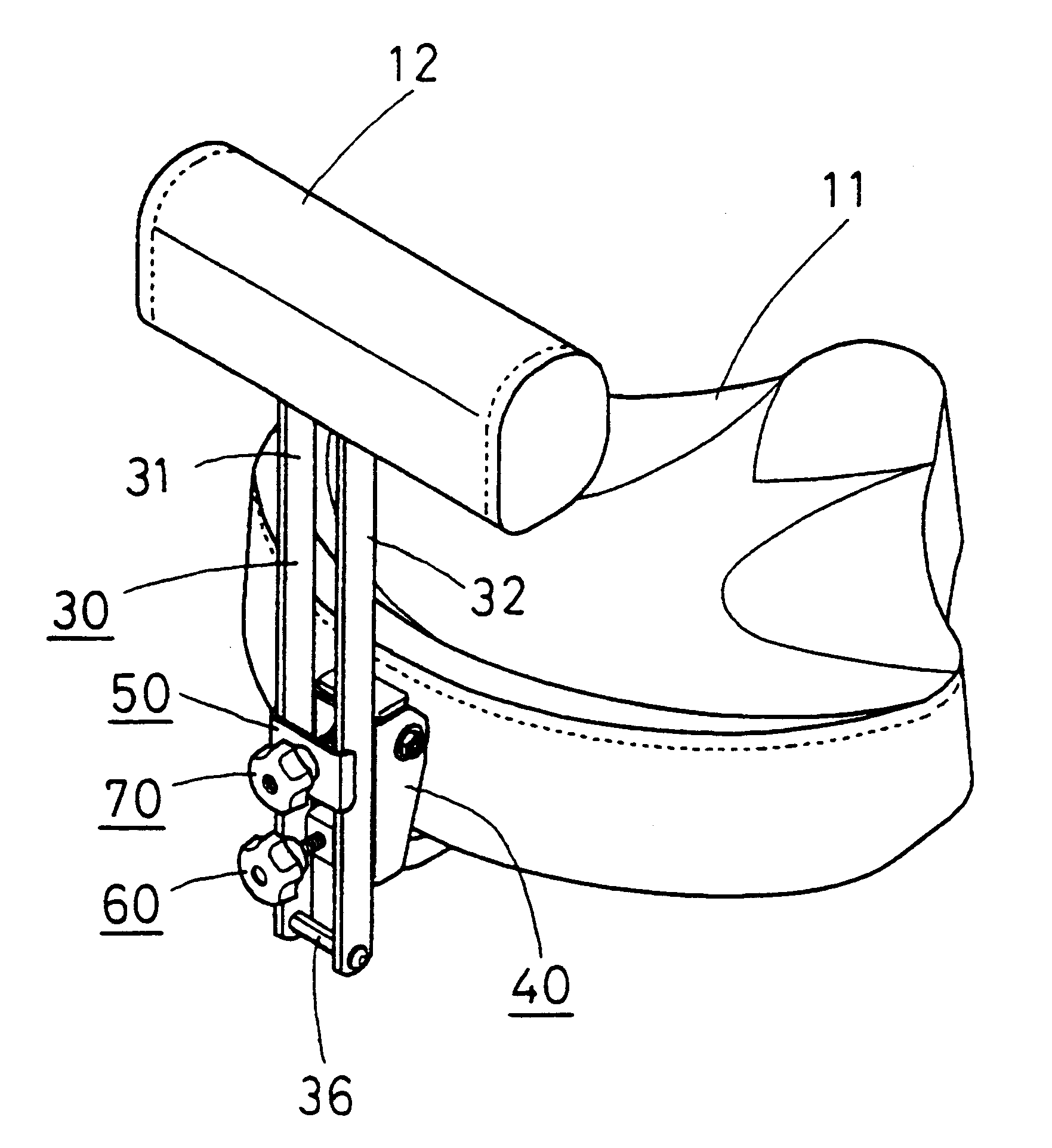
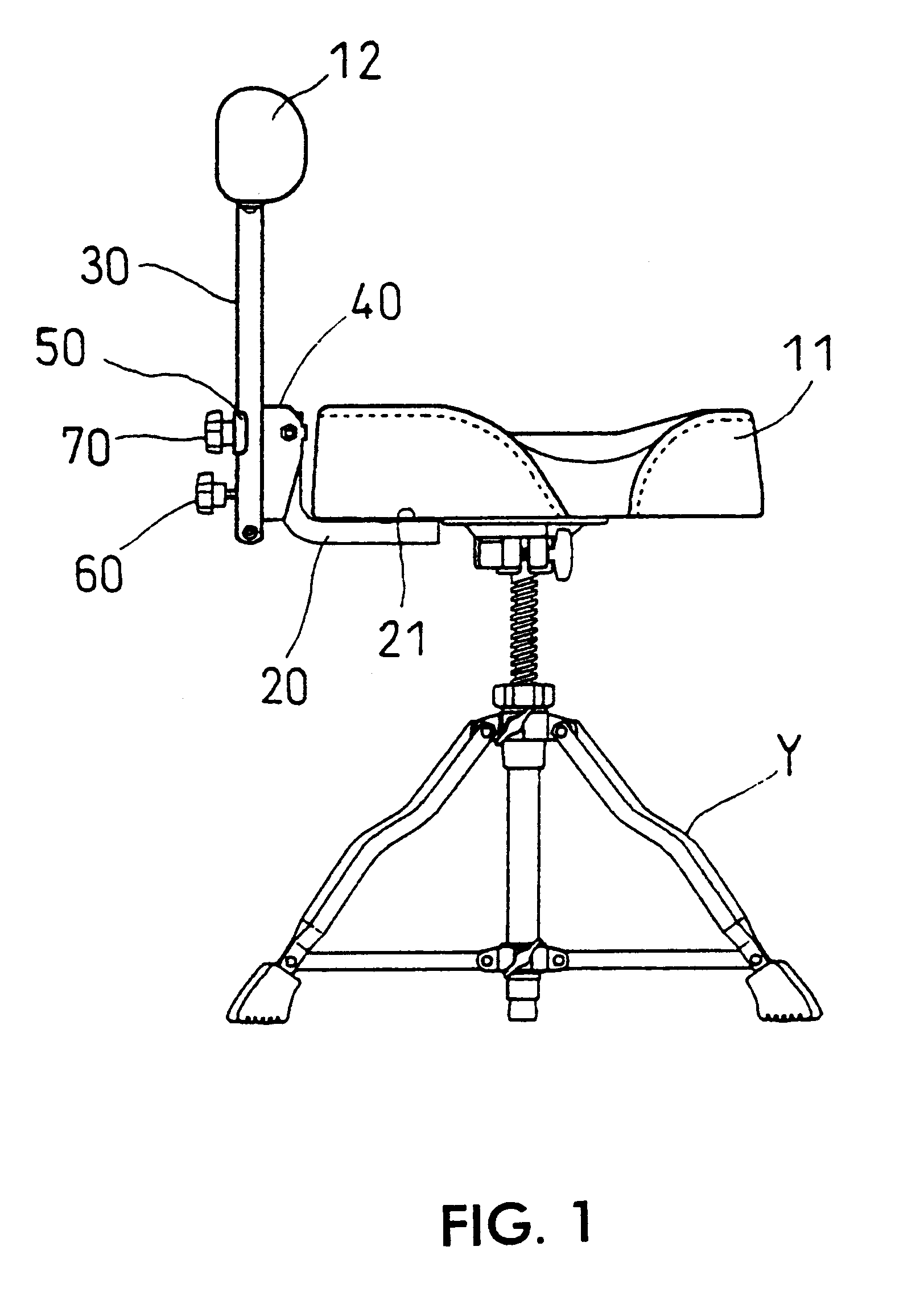
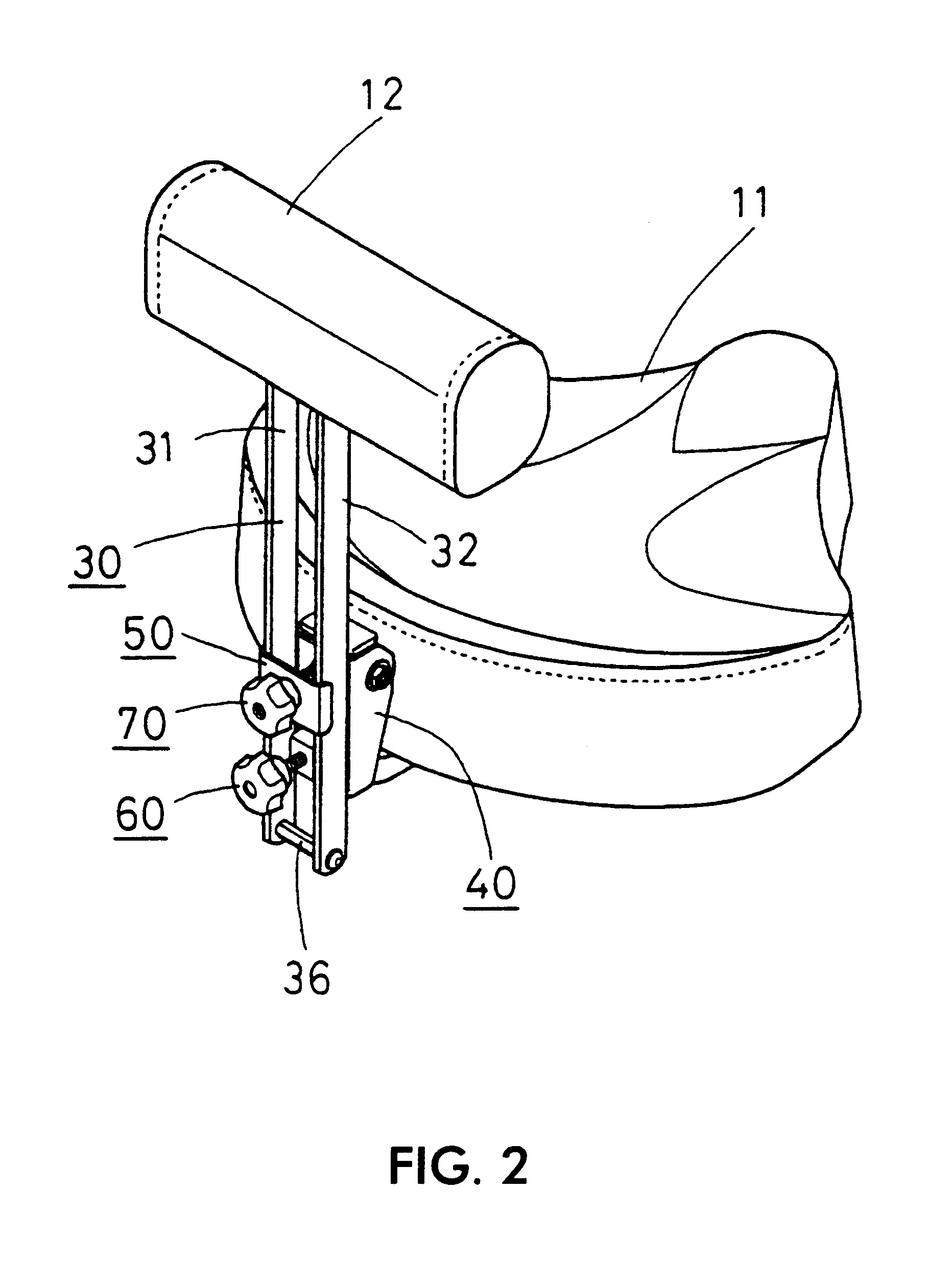
The backrest of a drum chair according to the invention has a structure enabling the backrest 12 to be freely adjustable in height and tilt angle with respect to the seat 11, and enabling easy dismantling. The backrest comprises a main base body 20, a backrest main body 30, an arm holder 40, an arm holding plate 50, a back and forth adjusting screw member 60 and an arm fixing nut 70.

In FIG. 1, the seat 11 has a concave-convex shape in consideration of user comfort. Legs Y beneath the seat 11 cause the drum chair to be supported at the center of the seat.

In FIGS. 1-3, the main base body 20 combines the backrest main body 30, which includes a backrest 12, with the seat 11 to form an integral body. The base body 20 is fixed to the seat 11. The body 20 includes an upstanding part 22 at the rear side of the seat 11. For example, the main base body 20 is L-shape as viewed from the side. It is fixed by installation screws 23 at the lower surface of the seat 11 through an installation plate...


PUM


Abstract

A backrest for a chair, particularly a drum performance chair, which backrest can be adjusted both in height and in tilt angle with respect to the seat. The backrest has two upright arms. A base body is fixed to the chair seat. The base body has an upstanding part. A holder is supported on the upstanding part of the base body. The holder includes an arm sliding part which engage the backrest arms. The arm holder is pivotable about an axis. A holding plate is screw tightened selectively for holding the arms of the backrest at the selected height or loosened to permit the arms of the backrest to be changed in height. A front and back adjusting screw extending from the holder has a contact part that engages the base body. The degree of tightening of the adjusting screw with respect to the holder determines the tilt angle of the holder and the backrest.

Description

The present invention relates to the backrest for a chair, and particularly for a drum chair.A backrest of a drum chair is used by a performer to rest between drum performances or to mitigate the instability of his posture by placing both of his legs on the pedal part simultaneously in connection with the use of a twin-bass or a twin drum pedal.DESCRIPTION OF A PRIOR ART EMBODIMENTThe backrest of a drum chair is ordinarily a normal backrest used for an office chair or a business chair. The drum chair 90 shown in FIGS. 9 and 10 is comprised of a backrest 91, an L-shaped arm 93 and a seat 97. One end of the L-shaped arm 93 is inserted into a holder 95 on the lower surface of the seat 97, where the L-shaped arm 93 is fixed by a fixing screw F1. The position of the backrest in the back and forth direction with respect to the seat 97 is set by adjusting the depth of insertion of the L-shaped arm 93 into the holder.At the other end of the L-shaped arm 93, the backrest 91 is fixed by a fix...

Claims


Application Information

Patent Timeline
IPC IPC(8): A47C7/40A47C9/08A47C7/42A47C9/00A47C7/44A47C7/48
CPCA47C7/402A47C7/42A47C9/08
Inventor HOSHINO, YOSHIHIRO
Owner HOSHINO GAKKI COMPANY LIMITED
Why Eureka
Try Eureka