Constant flow valve

a constant flow, valve technology, applied in the direction of valve operating means/release devices, process and machine control, etc., can solve the problems of excessive fluid application, fluid drift from the intended target, wasteful and excessive fluid application

Inactive Publication Date: 2001-04-03
GLOBAL AGRI TECH & ENG
View PDF39 Cites 79 Cited by
  • Summary
  • Abstract
  • Description
  • Claims
  • Application Information

AI Technical Summary

Problems solved by technology

Excessive pressure will overly atomize the fluid discharge, causing the fluid to drift from the intended target.
On the other hand, inadequate pressure will have the opposite effect, resulting in a wasteful excessive fluid application.

Method used


Image

  • Constant flow valve
  • Constant flow valve
  • Constant flow valve

Examples


Embodiment Construction

will now be provided with reference to the accompanying drawings, wherein:

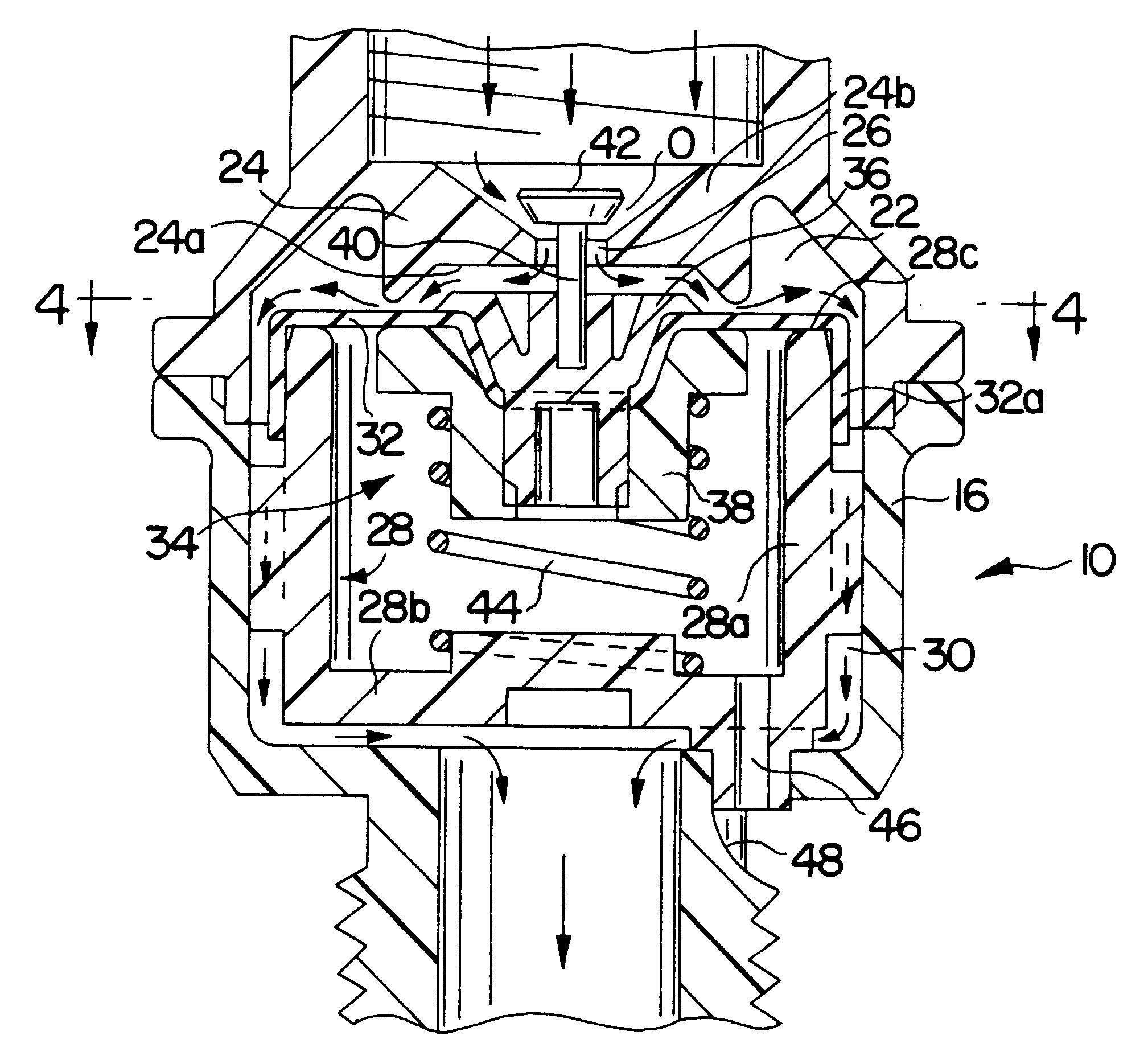
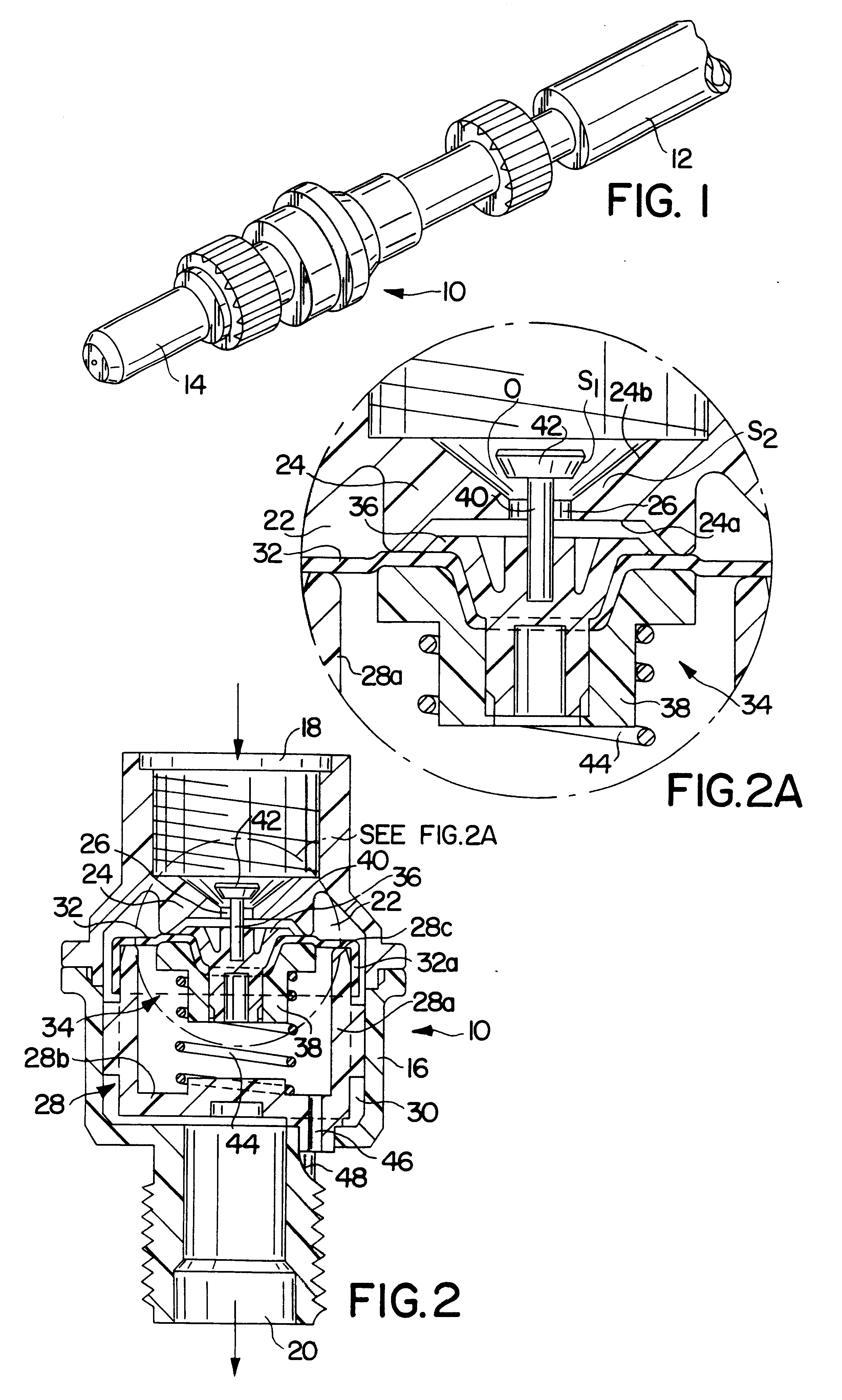
FIG. 1 is a perspective view of a regulating valve in accordance with the present invention shown interposed between a variable pressure fluid supply and a fluid outlet;

FIG. 2 is a longitudinal sectional view through the regulating valve;

FIG. 2A is an enlarged view of a portion of the valve shown in FIG. 2;

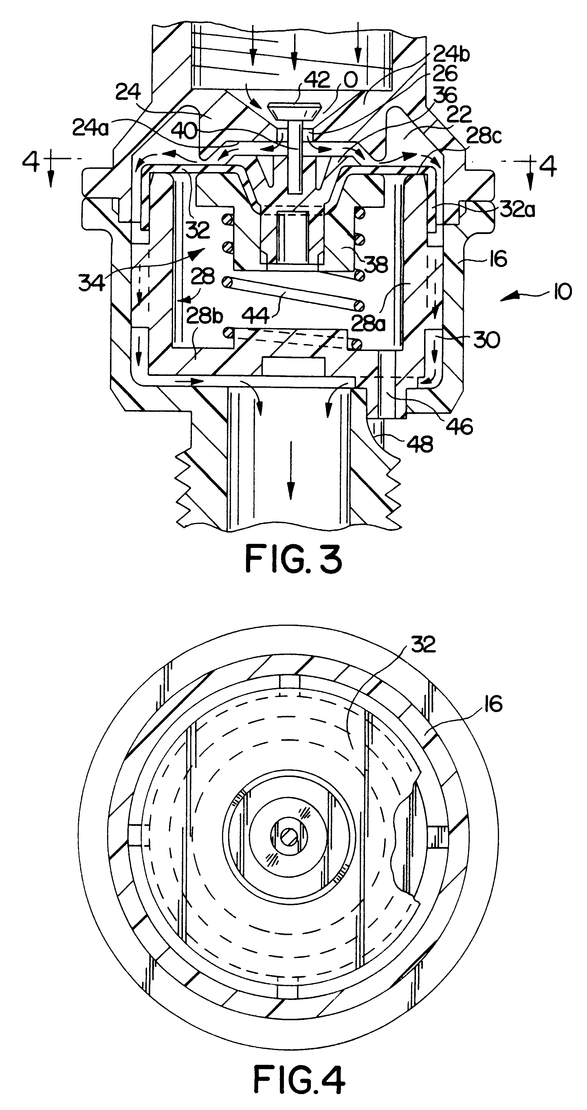
FIG. 3 is another enlarged longitudinal sectional view of the valve; and

FIG. 4 is a cross sectional view taken along line 4--4 of FIG. 3.

DETAILED DESCRIPTION OF PREFERRED EMBODIMENT

Referring initially to FIG. 1, a regulating valve in accordance with the present invention is generally depicted at 10 between a variable pressure fluid supply 12 and a fluid outlet 14. The supply 12 may typically be the discharge hose or wand of a compression or knapsack sprayer (not shown), and the outlet 14 may be a sprayer nozzle or the like. The valve 10 includes a housing 16 having axially aligned inlet and outlet ports 18, ...


PUM


Abstract

A regulating valve is disclosed for controlling the flow of fluid from a variable pressure fluid supply. The valve includes a diaphragm which is resiliently biased into a normally closed position, and which shifts to an open position when exposed to a fluid pressure above a predetermined minimum level.

Description

1. Field of the InventionThis invention relates to regulating valves used to control the flow of fluid between a variable pressure source and an applicator from which the fluid is discharged as a spray.2. Description of the Prior ArtPortable sprayers are widely employed in the application of herbicides and other chemical containing fluids. The sprayers may be of the "compression" type, where fluid is delivered from a pressurized tank, or they may be of the so-called "knapsack" type, where fluid is delivered from unpressurized tanks by manually operable pumps. In both cases, delivery pressure will vary. Excessive pressure will overly atomize the fluid discharge, causing the fluid to drift from the intended target. On the other hand, inadequate pressure will have the opposite effect, resulting in a wasteful excessive fluid application.The regulating valve of the present invention addresses these problems by automatically closing when fluid delivery pressure are below a predetermined m...

Claims


Application Information

Patent Timeline
Patent Type & Authority Patents(United States)
IPC IPC(8): G05D16/06G05D16/04G05D7/01G05D7/00
CPCG05D7/0106B05B12/087B05B9/0888Y10T137/7793Y10T137/7796Y10T137/7825
Inventor NEWTON, JOHN R.
Owner GLOBAL AGRI TECH & ENG
Why Eureka
Try Eureka