Electric connector having depressible contact pieces capable of conveying a relatively large current

Inactive Publication Date: 2001-06-05
HONDA TSUSHIN IND
View PDF4 Cites 81 Cited by
  • Summary
  • Abstract
  • Description
  • Claims
  • Application Information

AI Technical Summary

Problems solved by technology

Disadvantageously the former depressible type of connector 23 has an increased electric resistance, and therefore it cannot permit a relatively large current

Method used


Image

  • Electric connector having depressible contact pieces capable of conveying a relatively large current
  • Electric connector having depressible contact pieces capable of conveying a relatively large current
  • Electric connector having depressible contact pieces capable of conveying a relatively large current

Examples


first embodiment

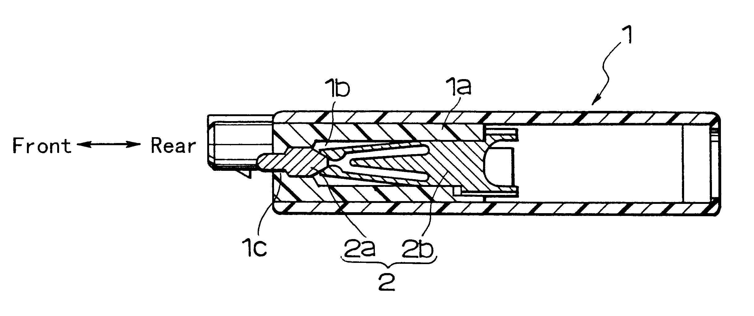
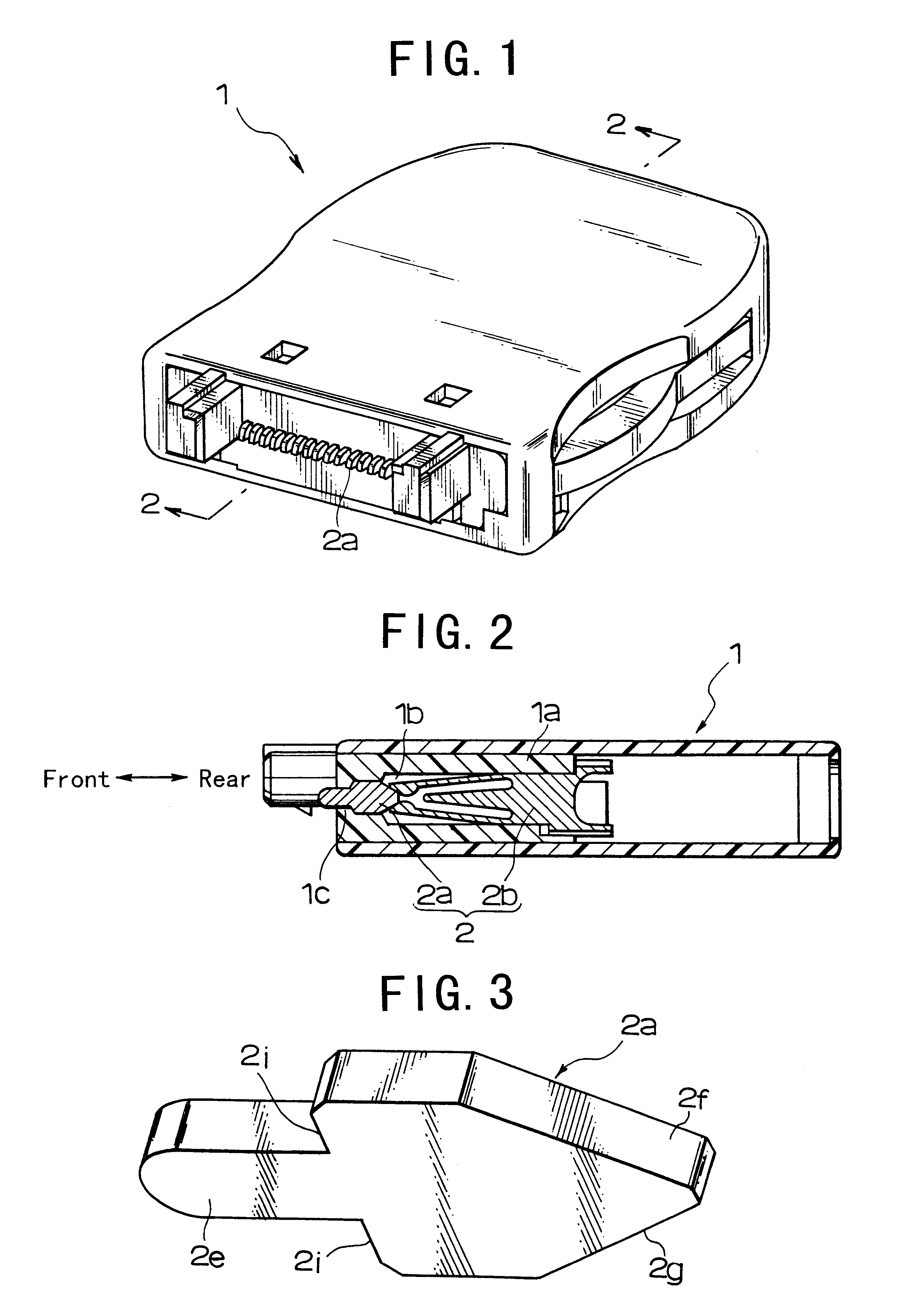
Referring to FIGS. 1 and 2, an electric connector according to the present invention is of female type. It comprises an insulating casing 1a having a plurality of contact pin slots 1b made therein and a corresponding plurality of probe pins 2 inserted in the contact pin slots 1b of the insulating casing. Each probe pin 2 is composed of a movable contact piece 2a and a stationary contact piece 2b.

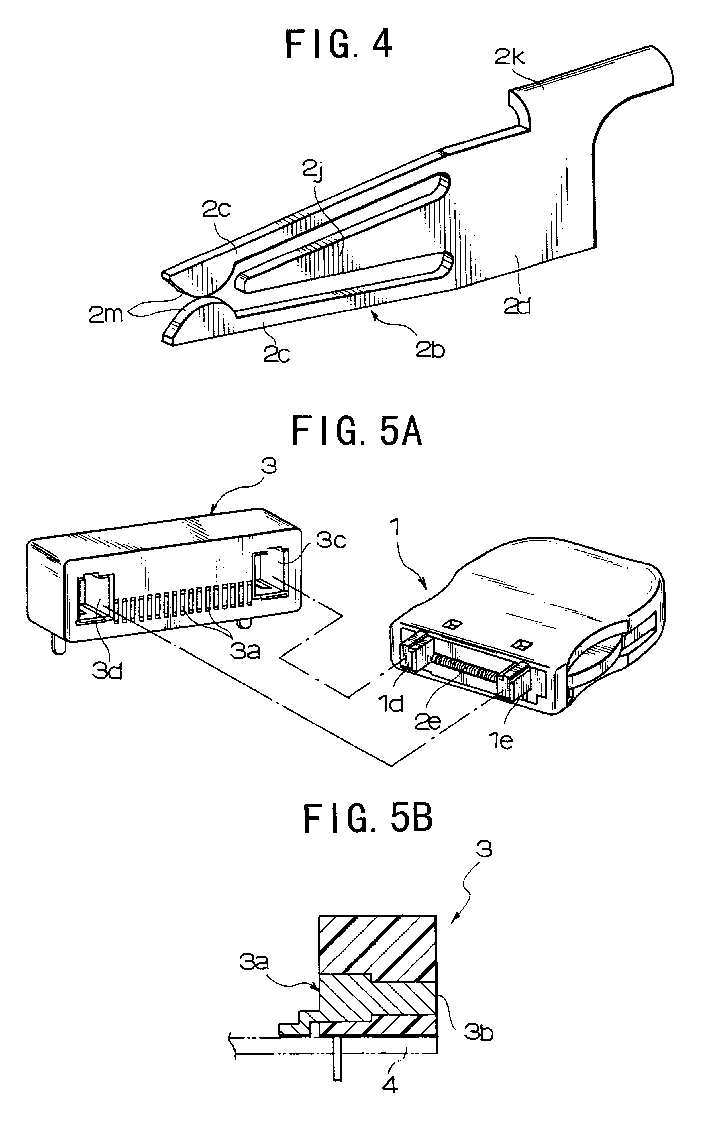
The probe pin 2 is made by stamping it from thin metal sheets (for instance, about 0.2 mm thick) with a metal die. As seen from FIGS. 2 and 3, the movable contact 2a comprises a front projection 2e and a rear convergence integrally connected to the front projection 2e. The front projection 2e of the movable contact 2a partly appears from one end opening lc of the pin slot 1b so that it may abuts against a counter contact such as a male contact 3a in FIGS. 5A and 5B. The rear convergence of the movable contact 2a is triangular in shape, and its tapering sides 2f and 2g converge to one common ...

second embodiment

Referring to FIG. 7, an electric connector according to the present invention is different only in that each movable contact piece 2a has shoulders 2p formed at the front projection-to-rear convergence transitions in place of the detent extension. The ends 2n of the opposite arms 2c of the bifurcate stationary contact piece 2b abut against the opposite shoulders 2p of the movable contact piece 2a, thereby preventing the movable contact piece 2a from invading deep too much in the pin slot 1b. The bifurcate stationary contact piece 2b provides a parallel-arrangement of current carrying passages so that an increased current may flow therethrough.

third embodiment

Referring to FIG. 8, an electric connector according to the present invention uses probe pins each comprising a movable bifurcate contact piece 2a and a stationary bifurcate contact piece 2b. The movable bifurcate contact piece 2a comprises a front projection having two opposite diverging arms extending rearward and having tapered inner sides 2f and 2g whereas a stationary bifurcate piece 2b having two opposite converging arms 2c and 2c extending forward from its base 2d. The diverging arms of the movable contact piece 2a embrace the converging arms 2c and 2c of the stationary contact piece 2b. Specifically when the movable bifurcate contact piece 2a is depressed, the diverging arms of the movable contact piece 2a bend the contact ends 2n of the converging arms 2c of the stationary bifurcate contact piece 2b inward, so that the converging arms 2c may avail themselves of the repulsive force thus caused to make a reliable electric connection between the movable and stationary contact ...


PUM


Abstract

Disclosed is an improved electric connector having depressible probe pins each comprising movable and stationary contact pieces. The movable contact piece comprises a front projection and a rear convergence integrally connected to the front projection. The probe pin is press-fitted in a selected pin slot in the insulating casing of the electric connector, allowing the front projection to partly appear from the selected pin slot. The stationary contact piece has two opposite arms extending from its base. The opposite arms of the stationary contact piece pinch the convergence of the movable contact piece, and withdrawal of the front projection of the movable contact piece causes the opposite arms to yieldingly open wide enough to allow the convergence of the movable contact piece to invade therebetween. The parallel-arrangement of current-carrying passages provided by the bifurcate stationary contact piece has the effect of increasing the current conducting capacity of the electric connector.

Description

1. Field of the InventionThe present invention relates to a male or female type of electric connector, and more particularly to an electric connector having depressible probe pins mounted in its insulating casing, the depressible probe pins being yieldingly depressed in the pin slots of the insulating casing when pushed against the contacts of a counter electric connector.2. Related ArtsReferring to FIG. 10, a conventional pin-depressible type of male or female connector 23 comprises an insulating casing 20 having a plurality of contact pin slots 21 made therein and a corresponding plurality of probe pins 22 inserted in the contact pin slots 21 of the insulating casing 20. Each probe pin 22 comprises a movable contact piece 22a and a stationary contact piece 22b integrally connected to the movable contact piece 22a via a zigzag spring 22c. Specifically the movable contact piece 22a appears partly from the contact pin slot 21, and is responsive to abutment on a counter contact (not s...

Claims


Application Information

Patent Timeline
IPC IPC(8): H01R13/24H01R13/22H01R24/00
CPCH01R13/2471H01R12/716H01R2201/16
Inventor FURUSAWA, SADATOSHINARUMO, KINZOTAKAHASHI, KENICHI
Owner HONDA TSUSHIN IND
Why Eureka
Try Eureka