Thermal printing

a printing apparatus and thermal printer technology, applied in the direction of printing, power drive mechanisms, instruments, etc., can solve the problems of difficult to grope for the insertion port of printing paper in a dark environment, user need to know well how to handle the thermal printer, and the user's visual confirmation might be difficul

Inactive Publication Date: 2001-06-19
SEIKO INSTR INC
View PDF2 Cites 56 Cited by
  • Summary
  • Abstract
  • Description
  • Claims
  • Application Information

AI Technical Summary

Problems solved by technology

However, these methods require a user to know well how to handle the thermal printer.
In particular, operability related to the insertion of the printing paper has had a big problem in that it is hard to grope for a printing paper insertion port

Method used


Image

  • Thermal printing
  • Thermal printing
  • Thermal printing

Examples


Embodiment Construction

A preferred embodiment of the present invention will be described below in detail with reference to the drawings.

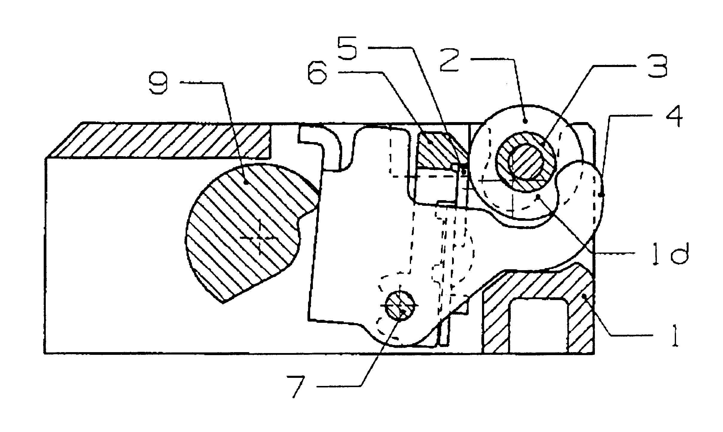
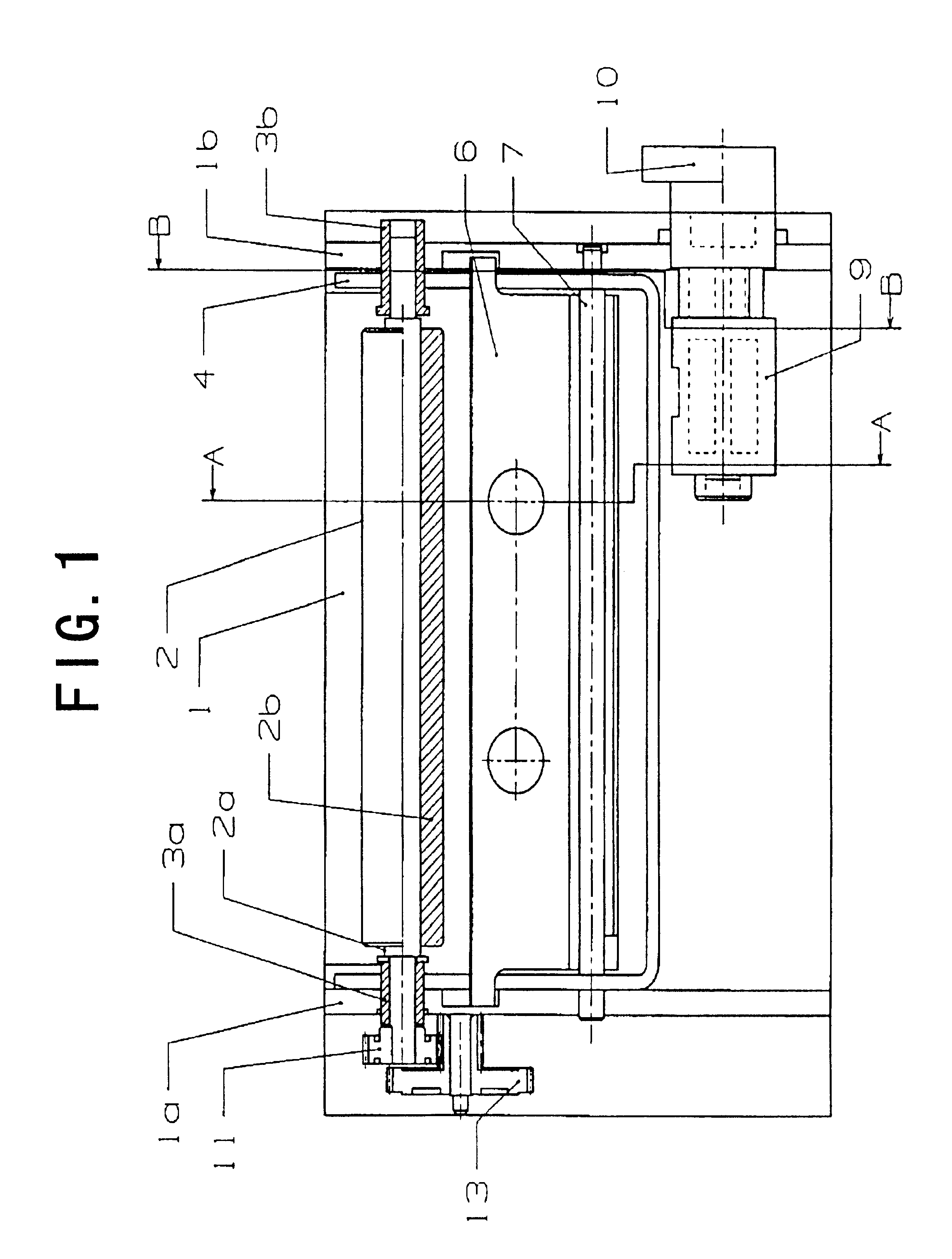
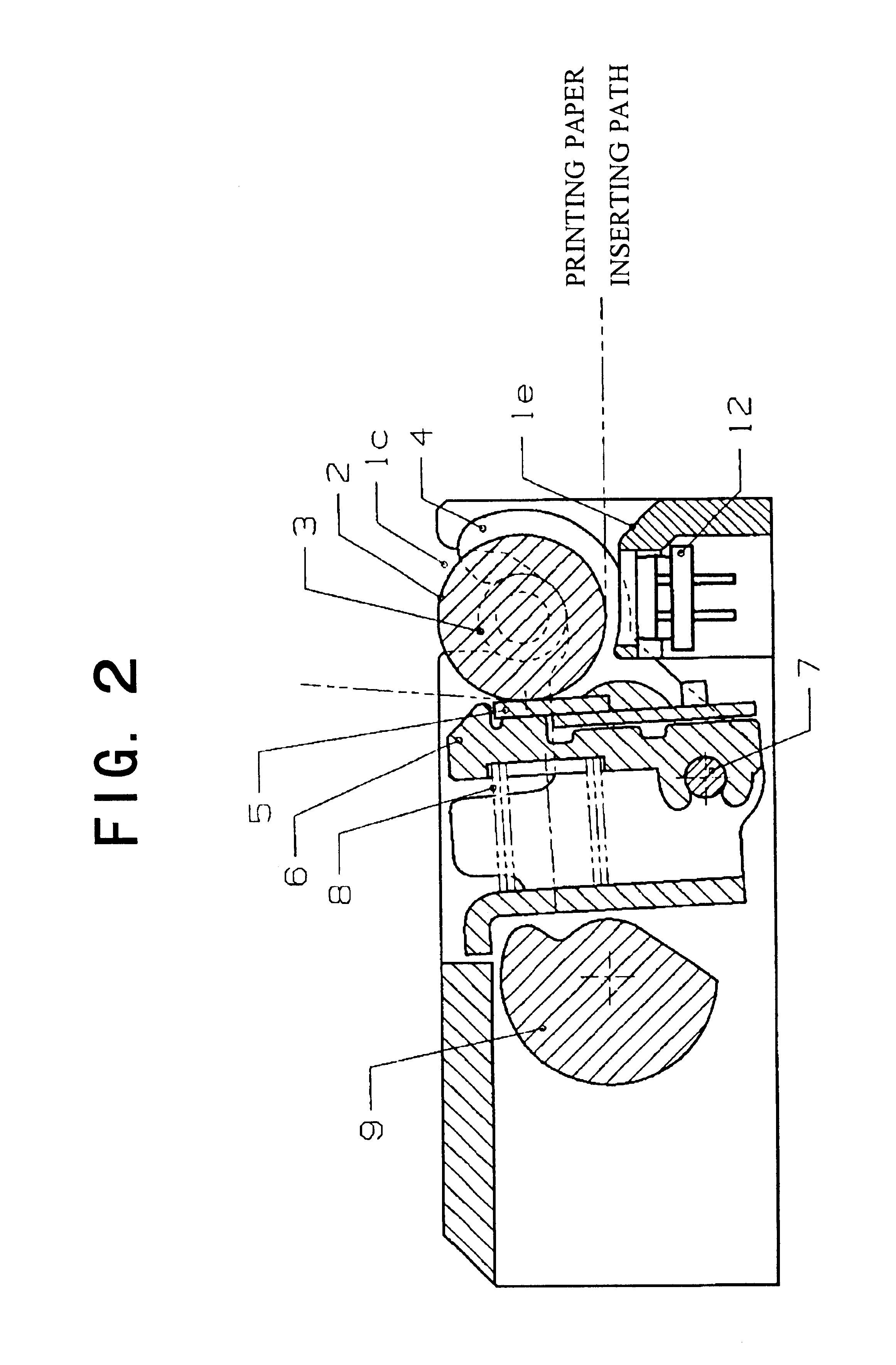
FIG. 1 is a partially sectional plan view showing an embodiment of the present invention, FIG. 2 is a side view taken along the line A--A in FIG. 1, and FIGS. 3 to 7 are side views taken along the line B--B in FIG. 1. These drawings are sectional views showing a main part in order to plainly illustrate the characteristic structure of a thermal printer according to the embodiment which will be described below. Moreover, FIG. 2 to FIG. 7 are not full sectional views but partially perspective and side views in order to easily represent the state in which a lock arm 4, a platen roller 2 and a thermal head 5 and a head support member 6 interact with one another and to prevent the drawings from being complicated.

In FIG. 1, the platen roller 2 is provided between side walls 1a and 1b of a body frame 1 of the printer. The body frame 1 is formed of plastic, and the platen roller 2...


PUM


Abstract

A conventional thermal printer has had a structure in which a platen roller cannot be removed from a frame. Therefore, it has been necessary to insert a printing paper between a thermal head and the platen roller. Thus, it has been hard to load the printing paper. In order to solve the problem, there has been devised means for engaging the platen roller with the frame by the biasing force of the thermal head pressing the platen roller to forcibly lift up the platen roller, thereby removing the platen roller. However, there have been problems in that great operating force is required for the removal and the precision in a platen roller support position is low. A frame is provided with a slit (1c) having such a shape as to guide a bearing of a platen roller (2), and the bearing of a platen roller (2) is pushed against the slit by a lock arm using the biasing force of a pressure spring (8) for causing a thermal head (5) to come in press-contact with the platen roller (2). Consequently, the platen roller (2) is supported.

Description

1. Field of the inventionThe present invention relates to a printing apparatus and a mechanism for removably supporting a platen roller when a printer head is brought into press-contact with the platen roller to interpose printing paper between the printer head and the platen roller, and more particularly, the invention relates to a thermal printing apparatus (thermal printer) capable of enhancing operability for the loading of the printing paper, head cleaning and the like.2. Description of the Related ArtA thermal printer is constituted to form an image on a thermal printing paper by using a thermal head.FIG. 8 shows an example of the structure of a conventional thermal printer and a printing paper inserting path. A platen roller 2 is rotatably supported to a body frame 1 through a bearing (not shown), and a thermal head 5 is rotated and biased to come in press-contact with the platen roller 2 by the biasing force of a pressure spring 8. The thermal head 5 can be separated from th...

Claims


Application Information

Patent Timeline
IPC IPC(8): B41J11/02B41J13/02B41J11/04B41J11/14B41J2/32B41J25/312B41J25/316
CPCB41J11/04B41J13/025
Inventor SEKIYA, HIROAKI
Owner SEIKO INSTR INC
Why Eureka
Try Eureka