Baby walker speed control caster

a technology for a baby walker, which is applied in the field of baby walker, can solve the problems of putting the baby in danger, unable to afford an obvious braking effect of a speed control caster, and hindering the wheel agility at a relatively low speed

Inactive Publication Date: 2002-04-23
KINGSTAR BABY CARRIAGES
View PDF10 Cites 13 Cited by
  • Summary
  • Abstract
  • Description
  • Claims
  • Application Information

AI Technical Summary

Problems solved by technology

However, most of the conventional baby walkers do not perform a self-braking effect, hence putting the baby in danger when the speed of the baby walker goes too high especially on a downhill or an uneven roadway.
1. The frictional force caused between the protruding arc 433 and the ring groove 42 can hardly afford an obvious braking effect for a speed control caster.
2. The protruding arc 433 tends to be deformed after the speed control caster is used for a period of time.
3. The fixing piece 43 does not revolve as the wheel 41 but swing about the convex shaft tube 45, thus hindering the wheel agility at a relatively low speed.
4. The conventional speed control caster has a complex structure resulting in a high-level damage rate and a high manufacturing cost.

Method used


Image

  • Baby walker speed control caster
  • Baby walker speed control caster
  • Baby walker speed control caster

Examples


Embodiment Construction

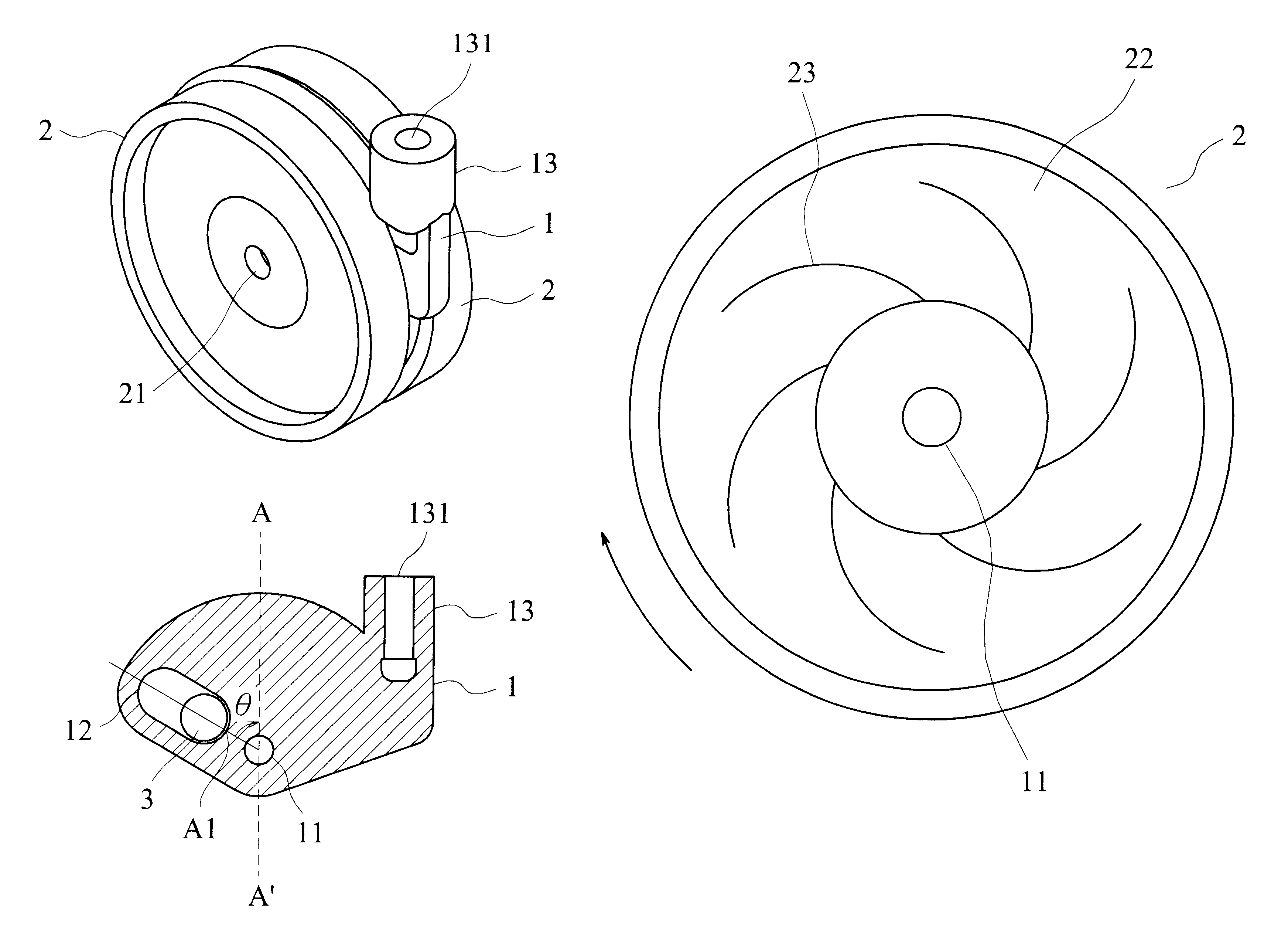
Referring to FIGS. 3A and 3B, the baby walker speed control caster according to the first embodiment of the invention includes a ball 3, a pair of wheels 2 formed with a plurality of spiral-shaped embossing curves 23 as shown in FIG. 4, and an axle piece 1 provided with a pivot hole 11, a through hole 12, and a pivot shaft 13.

The through hole 12 with the ball 3 in it is formed in an elongated elliptical shape whose long axis is at an angle .theta. to the vertical line AA' shown in FIG. 3B. Basically, the through hole 12 can be formed in an arbitrary shape as long as the ball 3 has enough space to move back and forth in it and the elongation of the through hole 12 is at an angle .theta. to the vertical line AA'. The appropriate angle .theta. is between 0 to 90 degrees.

As shown in FIGS. 5A and 5B, the axle piece 1 is sandwiched between both the wheels 2 such that a prolonged chamber 25 containing the ball 3 is formed by the through hole 12 and the inner walls of the wheels 2. Starting...


PUM


Abstract

A baby walker speed control caster. The speed control caster includes an axle piece, a pair of wheels symmetrically provided at either side of the axle piece, and a ball. The axle piece is provided with a pivot hole, a through hole, and a pivot shaft. Each wheel is formed in a thickness radially increasing respectively from the adjacency of the wheel center and is provided with a pivot hole at the center and a plurality of embossing curves at the inner side; in this way, the wheels are pivotably connected to each other by a pivot axle passing through the pivot holes of the wheels and the axle piece sandwiched between the wheels such that a chamber, containing the ball, is formed by the through hole of the axle piece and the inner walls of the wheels and the width between two inner walls increases radially from the adjacency of the wheel center. As the baby walker moves faster, the ball is squeezed between two inner walls of the wheels when the ball is swept toward the far side of the chamber by the embossing curves, thus producing a remarkable brake effect due to the friction between the axle piece and the wheels via the ball.

Description

A. Field of the InventionThe present invention relates to a baby walker, particularly to a baby walker speed control caster for a safety concern.B. Description of the Related ArtThe baby walker is commonly used for babies learning to walk. However, most of the conventional baby walkers do not perform a self-braking effect, hence putting the baby in danger when the speed of the baby walker goes too high especially on a downhill or an uneven roadway. Generally, the self-braking device for a baby walker can be realized as the speed control caster.Referring to FIGS. 1 and 2, a conventional speed control caster 40 for the baby walker generally includes a wheel 41, a ring groove 42 provided at one flank of the wheel 41 and formed with a wavy ball trough 421, a fixing piece 43, a ball 44, a convex shaft tube 45 having a through hole 451 and being integrally formed together with the ring groove 42 at the interior of the caster, and a shaft rod 46.As shown in FIGS. 1 and 2, the fixing pieces...

Claims


Application Information

Patent Timeline
Patent Type & Authority Patents(United States)
IPC IPC(8): A47D13/04A47D13/00B60B33/02B60B33/00
CPCA47D13/043B60B33/0028B60B33/0042B60B33/0049B60B33/021B60B33/0068B60B33/0073B60B33/0094B60B33/0057
Inventor CHENG, CHIH-CHING
Owner KINGSTAR BABY CARRIAGES
Why Eureka
Try Eureka