System and method for sensorless rotor tracking of induction machines

a sensorless rotor and induction machine technology, applied in the direction of dynamo-electric converter control, dynamo-electric gear control, dynamo-electric brake control, etc., can solve the problem of ineffective method at low speed, rotor shaft transducer tend to be a major source of failure and expense, and the impedance variation due to slotting is nearly undetectabl

Inactive Publication Date: 2002-05-14
WESTINGHOUSE AIR BRAKE TECH CORP
View PDF6 Cites 50 Cited by
  • Summary
  • Abstract
  • Description
  • Claims
  • Application Information

AI Technical Summary

Benefits of technology

Briefly, in accordance with one embodiment of the present invention, a drive system comprises a rotor position and velocity tracker adapted to decouple fundamental frequency effects o...

Problems solved by technology

Rotor shaft transducers tend to be a major source of failure and expense in ac machine drives.
In most induction machines smaller than 1000 hp, the rotor slots are skewed causing the impedance variation due to slotting to be nearly undetectable with the resolution of standard current and/or voltage feedback sensors currently used in motor drives.
Because both the amplitude and frequency of the slot-ripple-induced voltage were proportional to speed, the method was not successful at low speeds.
Furthermore direction of rotation could not be determined because quadrature signals were not available and the frequency of the tracked slot-ripple-induce...

Method used


Image

  • System and method for sensorless rotor tracking of induction machines
  • System and method for sensorless rotor tracking of induction machines
  • System and method for sensorless rotor tracking of induction machines

Examples


Embodiment Construction

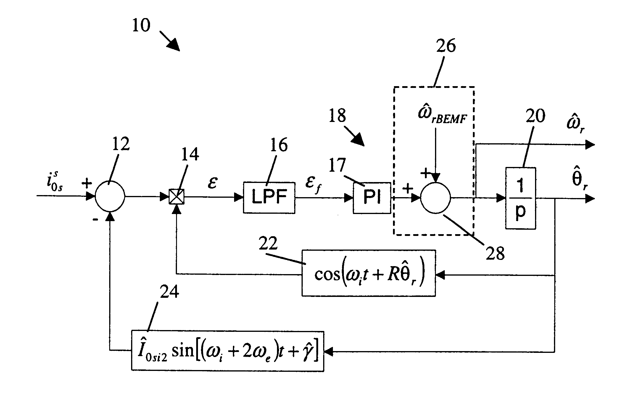
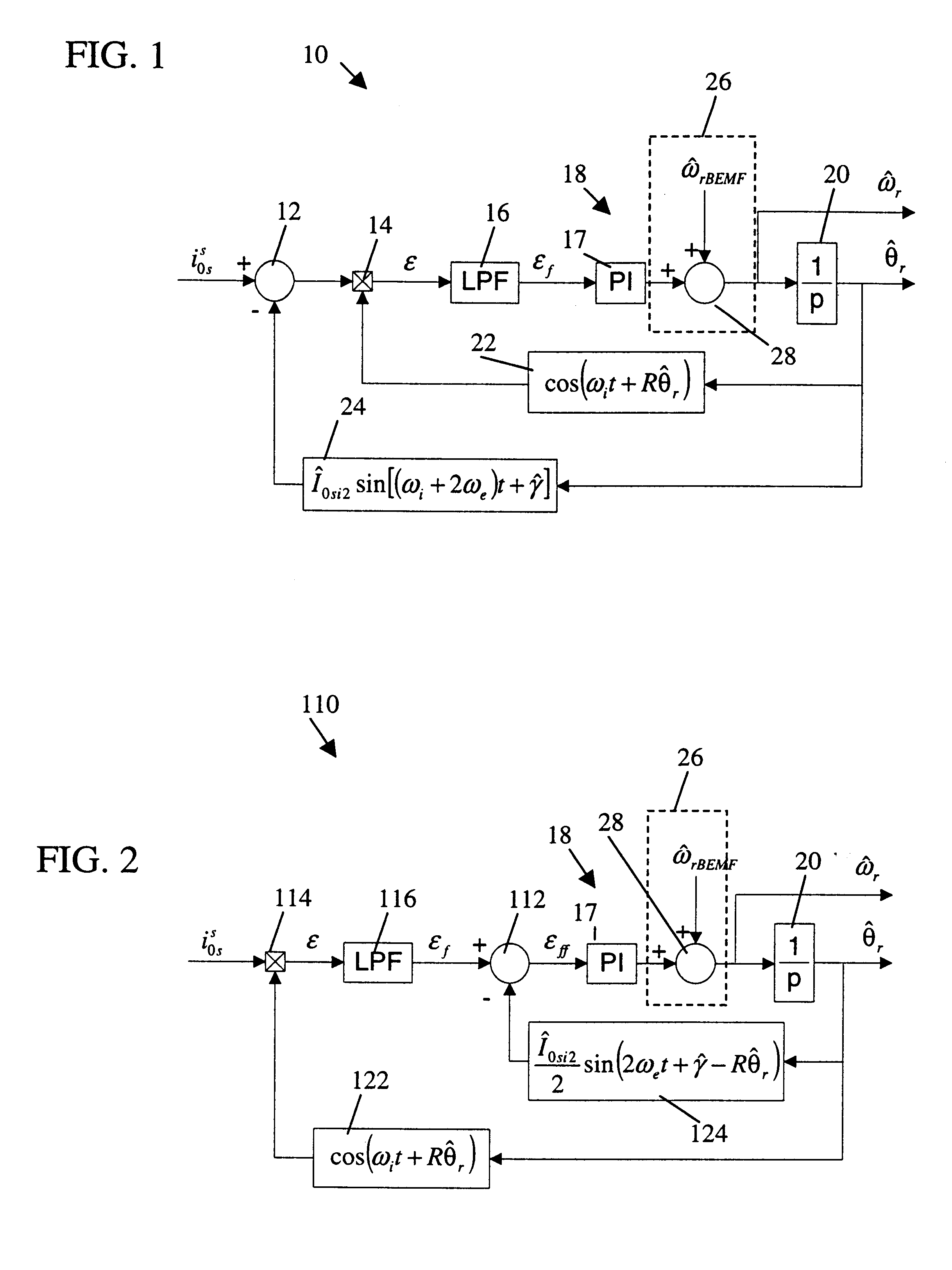
In one embodiment of the present invention, a drive system adapted for sensorless rotor tracking includes (a) machine drive controls for using a command signal and a high-frequency ac injected signal to provide ac drive power to an induction machine, and (b) a rotor position and velocity tracker adapted to decouple fundamental frequency effects of a zero sequence signal of the induction machine from the zero sequence signal and to use a resulting error signal to estimate a position and a velocity of a rotor of the induction machine.

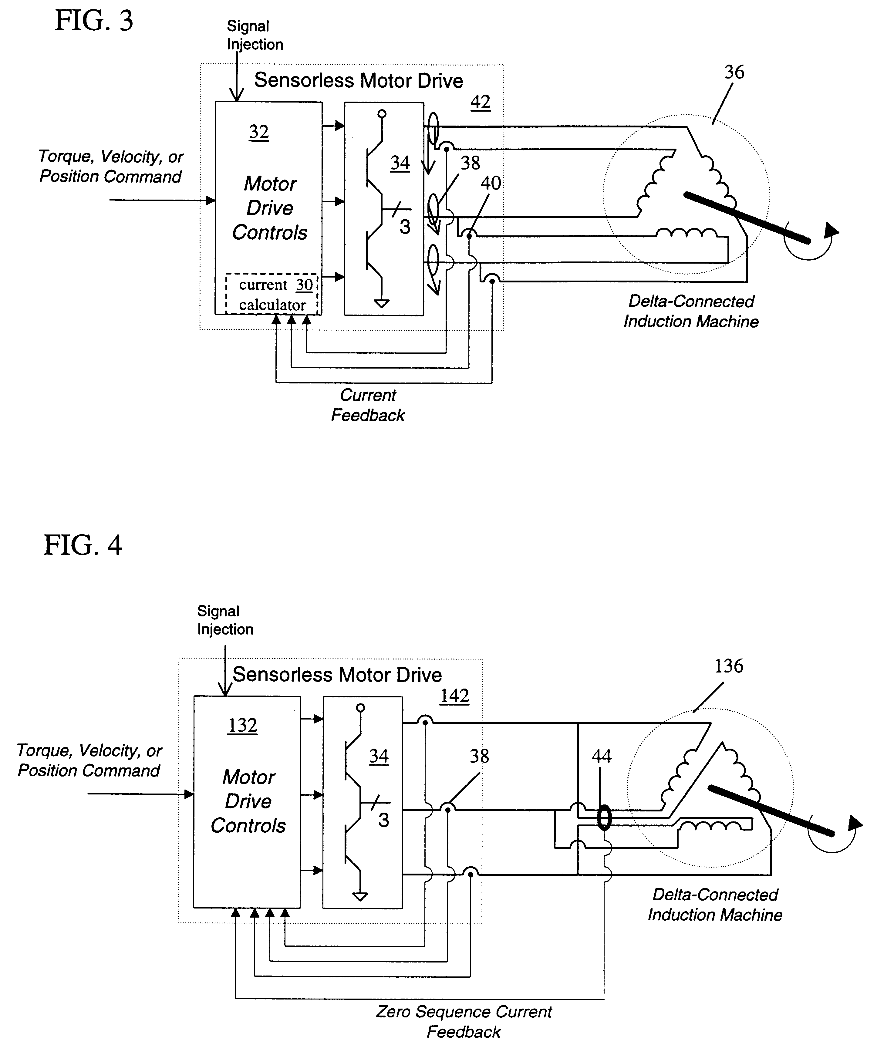
The present invention is applicable whether the ac induction machine is operated as a motor or as a generator and whether the ac induction machine is a delta-connected machine (described with respect to FIGS. 1-6) or a WYE-connected machine (described with respect to FIGS. 7-8). Although three-phase machines are depicted, the invention is also applicable to any polyphase machine, including, for example, two, five, and six phase machines. The invention can...


PUM


Abstract

A drive system comprises a rotor position and velocity tracker adapted to decouple fundamental frequency effects of a zero sequence signal of an induction machine from the zero sequence signal and to use a resulting error signal to estimate a position and a velocity of a rotor of the induction machine.

Description

The invention relates generally to induction machines and more particularly to sensorless rotor tracking of induction machines.The elimination of rotor shaft transducers such as rotor position and speed sensors is highly desirable to reduce cost, to reduce total motor package size, and to improve system reliability. Rotor shaft transducers tend to be a major source of failure and expense in ac machine drives.Jansen et al., U.S. Pat. Nos. 5,585,709 and 5,565,752, for example, describe a method of control whereby high frequency signal injection is used to track the rotor angular position and velocity of an induction machine having a rotor providing an impedance that varies with rotor position. Various means are presented whereby an induction machine rotor can be modified to introduce position dependent impedances that are detectable from the stator terminal via signal injection.Degner et al., "Using Multiple Saliencies for the Estimation of Flux, Position, and Velocity in AC Machines,...

Claims


Application Information

Patent Timeline
IPC IPC(8): H02P21/14
CPCH02P21/146H02P21/18
Inventor JANSEN, PATRICK LEEPREMERLANI, WILLIAM JAMESRIVERA, LUIS JOSE GARCES
Owner WESTINGHOUSE AIR BRAKE TECH CORP
Why Eureka
Try Eureka