Pruning shears with a lock device

Inactive Publication Date: 2002-07-16
JANG MING SHAN
View PDF12 Cites 76 Cited by
  • Summary
  • Abstract
  • Description
  • Claims
  • Application Information

AI Technical Summary

Problems solved by technology

However, because no positioning structure is applied to the block (36)

Method used


Image

  • Pruning shears with a lock device
  • Pruning shears with a lock device
  • Pruning shears with a lock device

Examples


Embodiment Construction

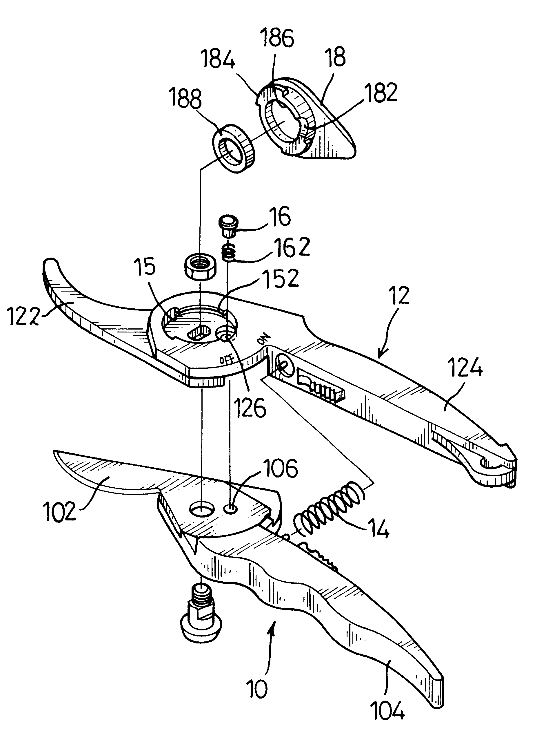
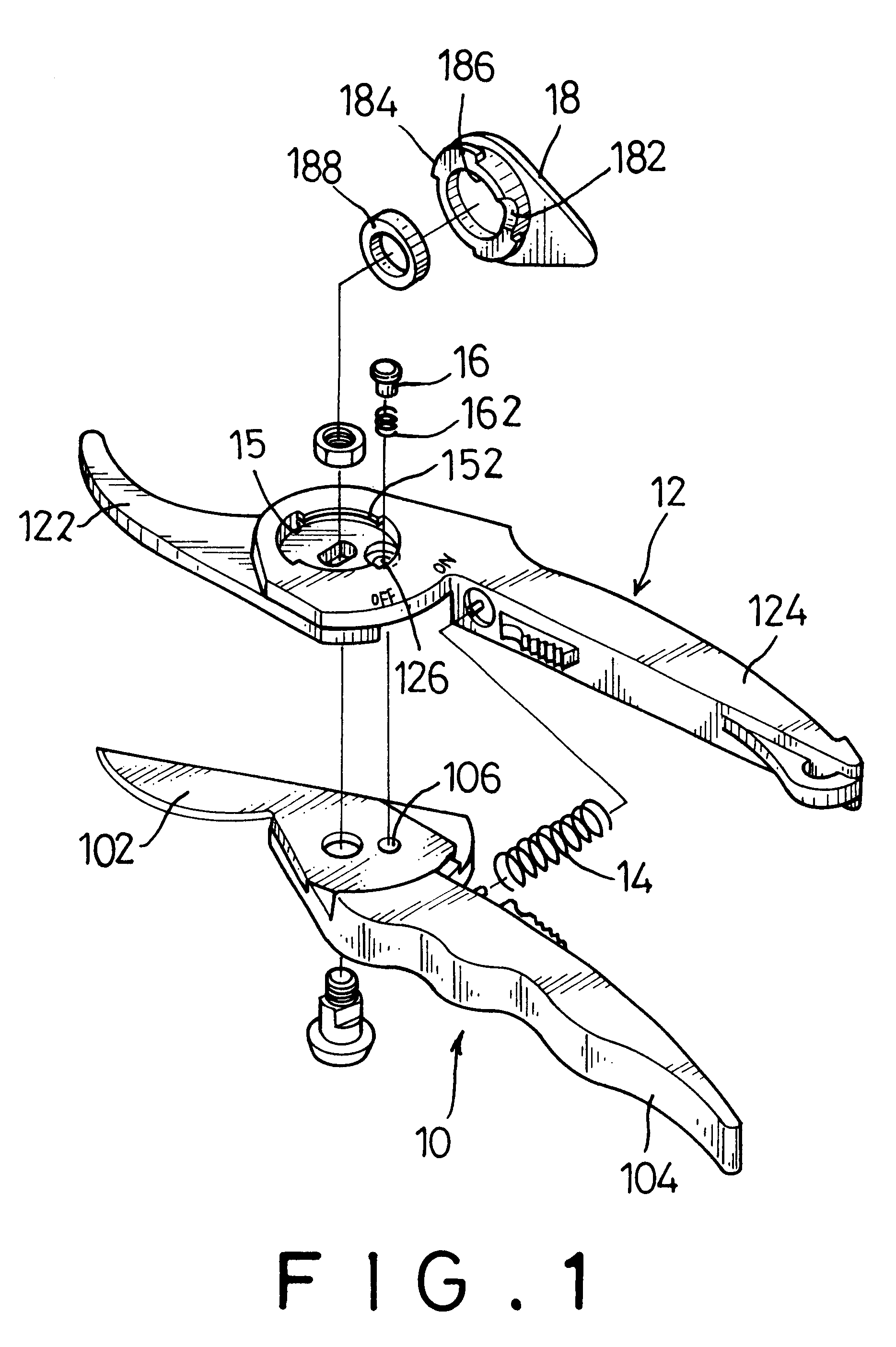
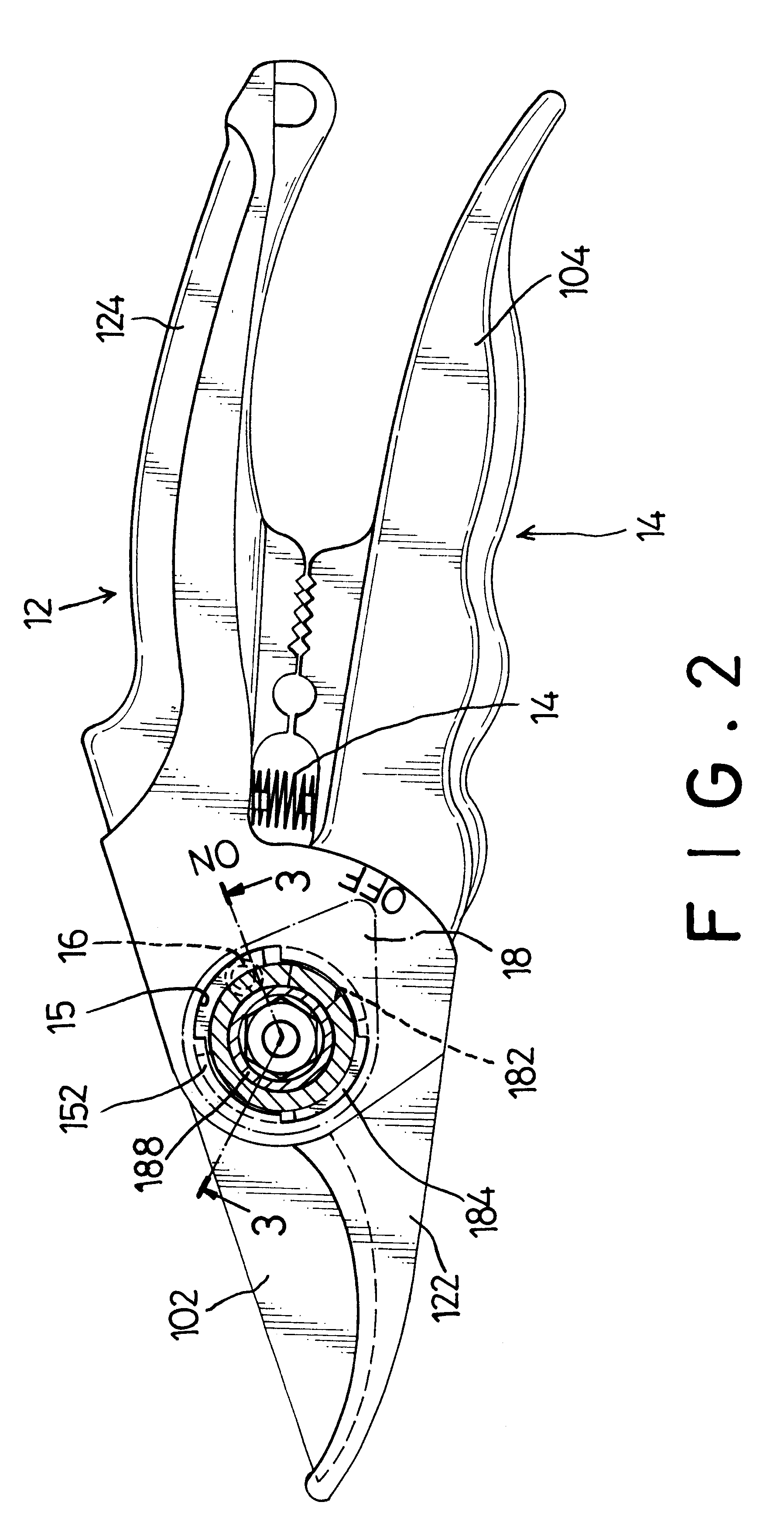
With reference to FIG. 1, a pair of pruning shears in accordance with the present invention comprises two bodies (10,12) pivotally mounted together with a pivot (not numbered), a spring (14) and a lock device arranged near the pivot. Each body (10,12) has a cutting end (102,122) formed on one end thereof and a handle (104,124) on another end. The spring (14) is connected between the handles (104,124) of the bodies (10,12) to provide a biasing force to keep distal ends of the handles (104, 124) far away from each other.

The lock device comprises a step hole (126), a locking hole (106), a latch post (16), a biasing member (162) and a knob (18). The step hole (126) is defined in one of the bodies, in this embodiment (12), near the pivot. The locking hole (106) is defined in the other one of the bodies (14) to align with the step hole (126) when the bodies (10,12) are pushed to close. The latch post (16) is moveably mounted in the step hole (126). The biasing member (162) is received in ...


PUM


Abstract

A pair of pruning shears has two bodies pivotally mounted together with a pivot, a spring connected between the bodies, and a lock device arranged near the pivot. The lock device comprises a step hole defined in one of the bodies near the pivot, a locking hole defined in the other body, a latch post moveably mounted in the step hole, a biasing member to support the latch post, and a knob. The knob is rotatably mounted on the body with the step hole. The knob has a bottom abutting the latch post and a cavity defined in the bottom. When the bodies are pushed toward to each other, the step hole will align with the locking hole. The latch post can be pushed to engage with the locking hole by the bottom of the knob. This can provide a secure positioning effect to the latch post. The latch post will not escape from the locking hole when the pruning shears bump with another object.

Description

1. Field of the InventionThe present invention relates to a pair of pruning shears, and more particularly to a pair of pruning shears having a lock device to securely hold the shears in a pushed position.2. Description of Related ArtWith reference to FIG. 6, a pair of conventional pruning shears in accordance with the prior art comprises two bodies (30,32) pivotally mounted together with a pivot. Each body (30,32) has a cutting end (302,322) formed on one end thereof and a handle (304,324) on another end. A spring (34) is connected between the handles (304,324) of the bodies (30,32) to provide a biasing force to push the handles (304,324) far away from each other. Therefore, the cutting ends (302,322) of the bodies (30,32) will keep in an open condition by the biasing force of the spring (34). However, a user, especially a child, is easily cut by the open cutting ends (302,322) of the bodies (30,32) when he or she holds the pruning shears in play. Consequently, a lock device is alwa...

Claims


Application Information

Patent Timeline
IPC IPC(8): A01G3/00A01G3/02B26B13/16B26B13/00
CPCA01G3/02B26B13/16
Inventor JANG, MING-SHAN
Owner JANG MING SHAN
Why Eureka
Try Eureka