
Eureka
For R&D, Eureka makes reading and utilizing patents & technical documents easy.
Eureka AIR
Designed for self-driven R&D workflows. Generate viable solutions, solve complex R&D challenges, empower your innovation with AI.

Eureka Materials
Designed for material experts only. Revolutionize your material R&D, from search, analyze, to developing new materials.

TechResearch
Generate reliable direction feasibility study reports for your R&D in just a few steps.

TechSeek
Discover and master advanced knowledge NOW. Basics, ideas, possibilities, all at once.

TechMind
As an expert in R&D Theories, TechMind can generates customized viable solutions instantly.

TechRisk
Analyze your overall solution with one click, know your potential R&D risks in advance.

TechMonitor
Get weekly tech updates, stay abreast of the latest tech innovations and key insights.
Air bag system with quick disconnect coupling
- Summary
- Abstract
- Description
- Claims
- Application Information
AI Technical Summary
Problems solved by technology
Method used
Image

Examples
first embodiment
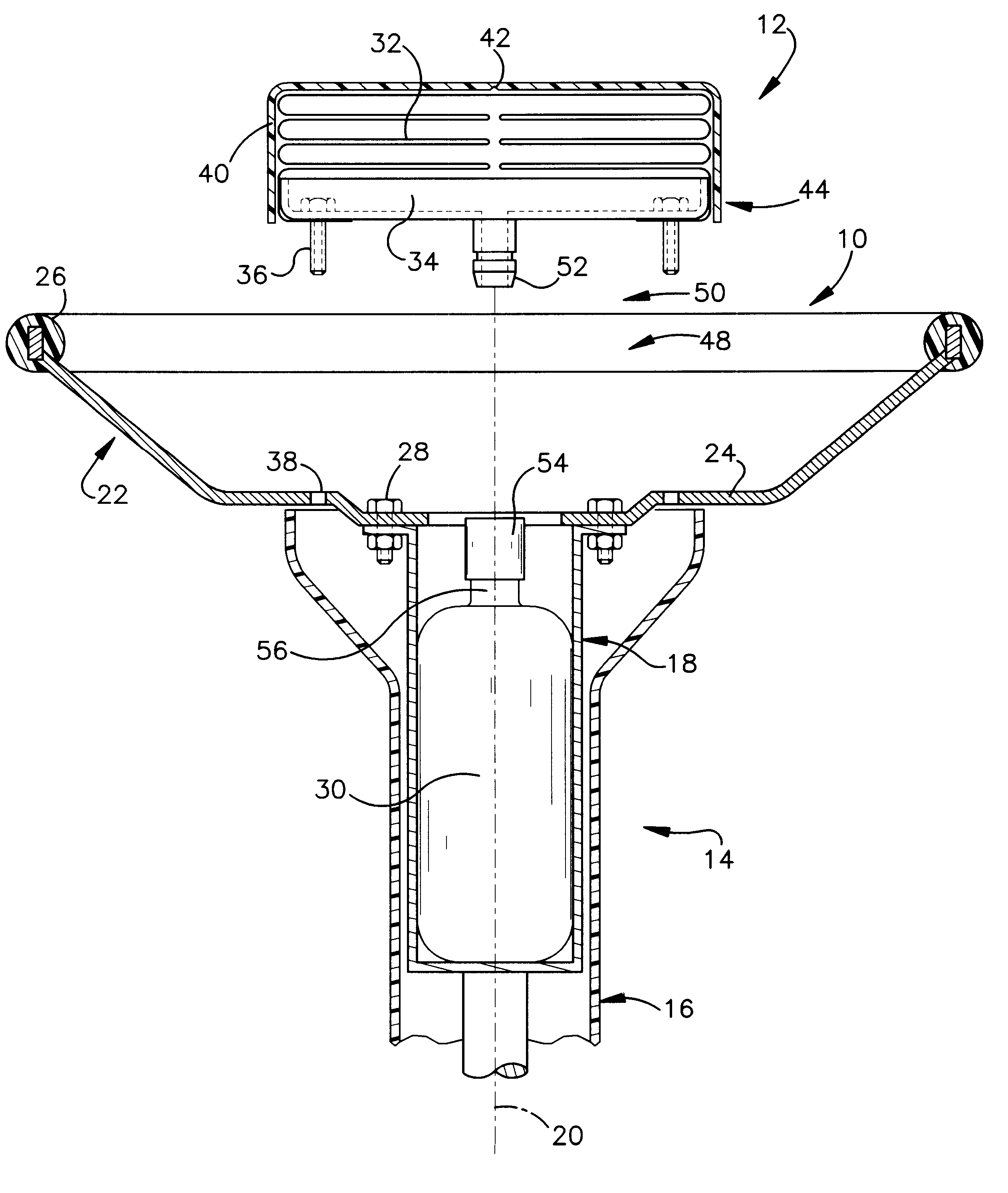
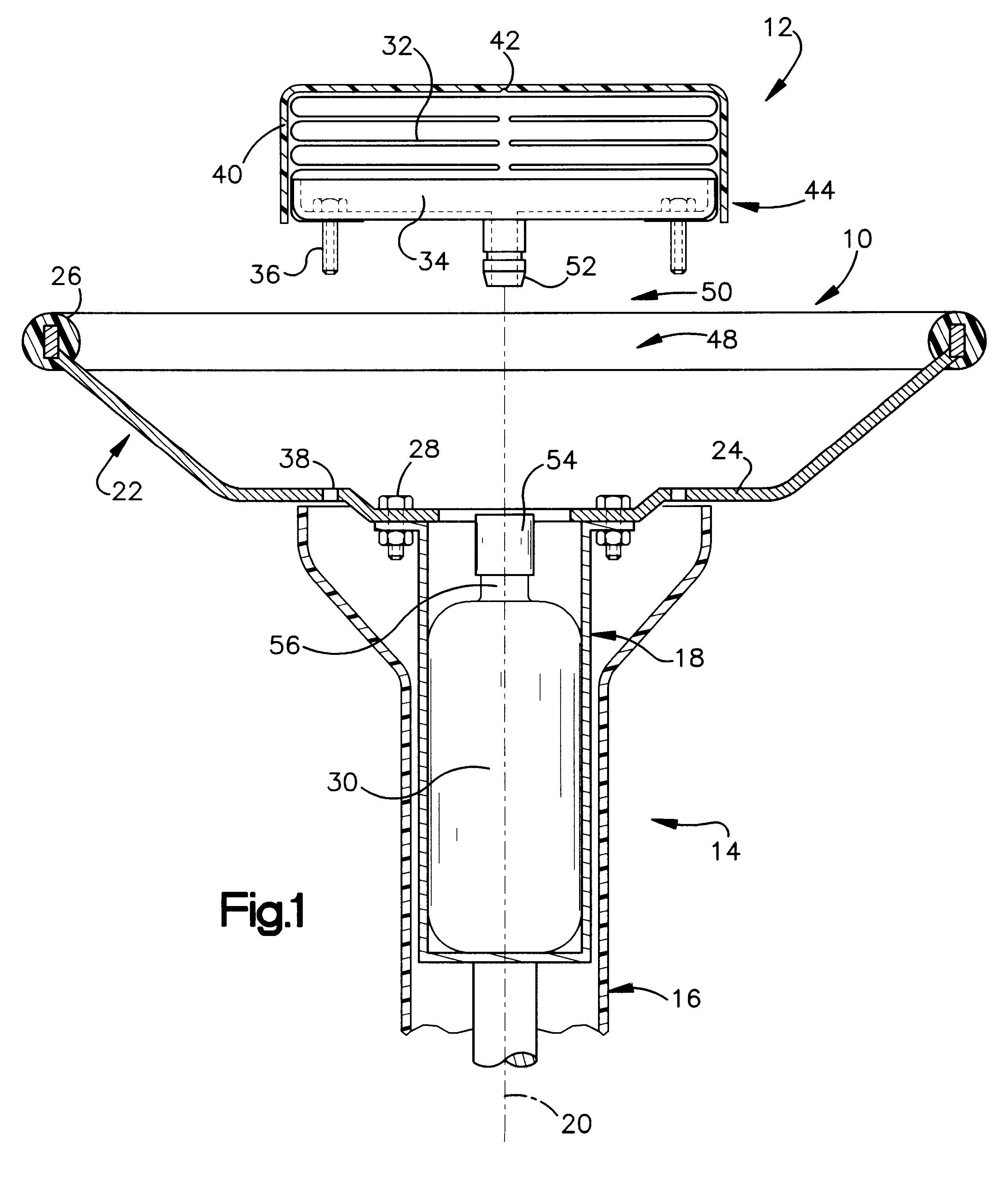
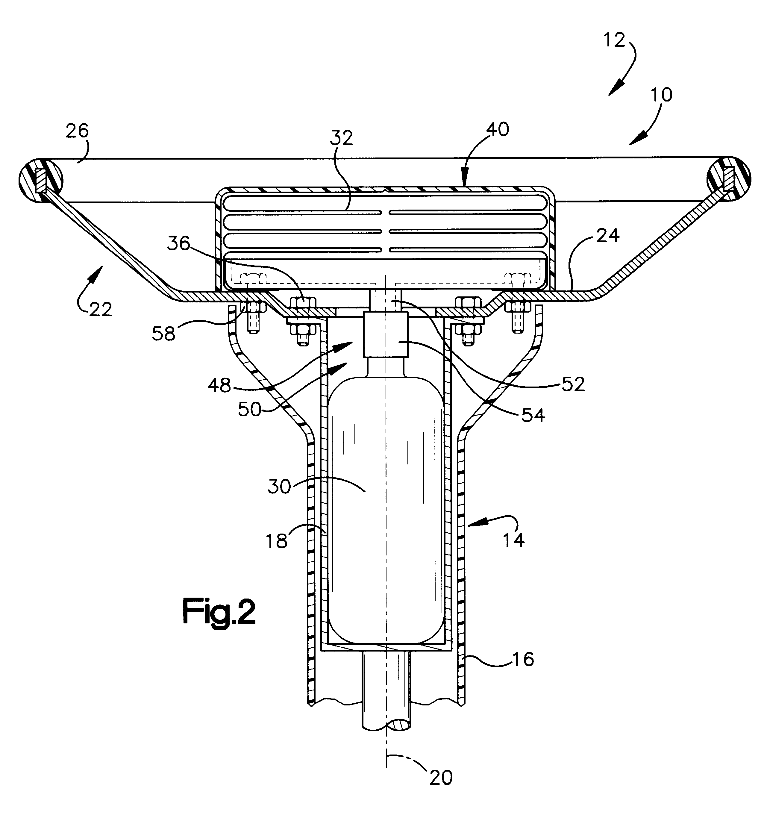
The present invention relates to a vehicle occupant protection apparatus. In particular, this invention relates to an apparatus including an inflatable vehicle occupant protection device, an inflator, and a coupling for connecting the protection device with the inflator. The present invention is applicable to various occupant protection apparatuses. As representative of the invention, FIG. 1 illustrates a vehicle occupant protection apparatus 10 in accordance with the invention.
The apparatus 10 is mounted in a vehicle 12 which includes a steering column 14. The steering column 14 has a fixed portion 16 and a movable portion 18. The movable portion 18 of the steering column 14 is disposed radially inward of the fixed portion 16 of the steering column. The movable portion 18 of the steering column 14 is supported on the fixed portion 16 of the steering column for rotation relative to the fixed portion about a steering axis 20.
The movable portion 18 of the steering column 14 supports a...
second embodiment
FIG. 3 illustrates a vehicle occupant protection apparatus 60 in accordance with the invention. The occupant protection apparatus 60 is mounted in a vehicle 62, which includes an instrument panel 64. The instrument panel 64 has a fixed support portion 66, which, as shown schematically in FIG. 3, includes at least two parts 68 and 70. The instrument panel 64 also includes a trim pad or cover 72. The cover 72 has a predetermined weakened portion, or rupturable portion, 74 disposed between two movable portions 76 and 78 of the cover.
The occupant protection apparatus 60 includes an air bag 80 and an inflator 82. The inflator 82 is supported on the one part 69 of the fixed portion 66 of the instrument panel 64. The inflator 82 can be the same type of inflator as described above with reference to the first embodiment of the invention. The air bag 80 is supported on the other part 70 of the fixed portion 66 of the instrument panel 64, at a location remote from the inflator 82, behind the m...
third embodiment
FIG. 4 illustrates a vehicle occupant protection apparatus 100 in accordance with the invention. The apparatus 100 is mounted in a vehicle 102, which includes a seat 104. The seat 104 includes a seat bottom cushion 106 and a seat back 108.
The seat back 108 includes a seat frame member 110 having a tubular construction. An outer side portion 112 of the seat frame member 110 extends generally vertically in the seat back 108, inside the outboard side bolster 114 of the seat 104. The side bolster 114 includes a fabric or leather covering material 116 having a predetermined weakened portion (not shown).
The apparatus 100 includes an air bag 120 and an inflator 122. A lower part 124 of the outer side portion 112 of the seat frame member 110 supports the inflator 122. The inflator 122 can be the same type of inflator as described above with reference to the first embodiment of the invention. A quick disconnect coupling 126 connects the inflator 122 in fluid communication with the interior o...
PUM
 Abstract
Description
Claims
Application Information
 - R&D Engineer
- R&D Manager
- IP Professional
- Industry Leading Data Capabilities
- Powerful AI technology
- Patent DNA Extraction
Browse by: Latest US Patents, China's latest patents, Technical Efficacy Thesaurus, Application Domain, Technology Topic, Popular Technical Reports.
© 2024 PatSnap. All rights reserved.Legal|Privacy policy|Modern Slavery Act Transparency Statement|Sitemap|About US| Contact US: help@patsnap.com