Communication system, article and method of configuring and establishing a connection therein

a communication system and communication system technology, applied in the field of communication systems, can solve problems such as messages being lost or sent to the wrong destination, present systems are deficient in their operation, and system operation is compromised

Inactive Publication Date: 2002-09-10
RPX CLEARINGHOUSE
View PDF6 Cites 11 Cited by
  • Summary
  • Abstract
  • Description
  • Claims
  • Application Information

AI Technical Summary

Problems solved by technology

Present systems are, however, deficient in their operation since they work on an assumption that each object is always available once at least one portion of the related information is downloaded to the intelligent peripheral from the controller.
Consequently, although a valid object may not therefore exist, the routing mechanism can get tied-up in an endless search loop whereby system operation is compromised.
Moreover, since the intelligent peripheral effectively has direct access to configuration data, the routing algorithm may make decisions based on a partially configured object that results in messages being lost or sent to a wrong destination.
Unfortunately, present systems are also sensitive to the order in which configuration messages are received by the intelligent peripheral.
In fact, configuration messages must be received in a pre-set order otherwise messages can be lost or the system can be mis-configured, with the later mis-configuration usually undetectable.
Unfortunately, pre-allocation requires the use of all available memory regardless of the complexity of the network configuration.
Consequently, additional memory and processing capacity must be provided to the intelligent peripheral if a system up-grade is required by a network operator; this is usually expensive and inevitably leads to some down-time for reconfiguration.

Method used


Image

  • Communication system, article and method of configuring and establishing a connection therein
  • Communication system, article and method of configuring and establishing a connection therein
  • Communication system, article and method of configuring and establishing a connection therein

Examples


Embodiment Construction

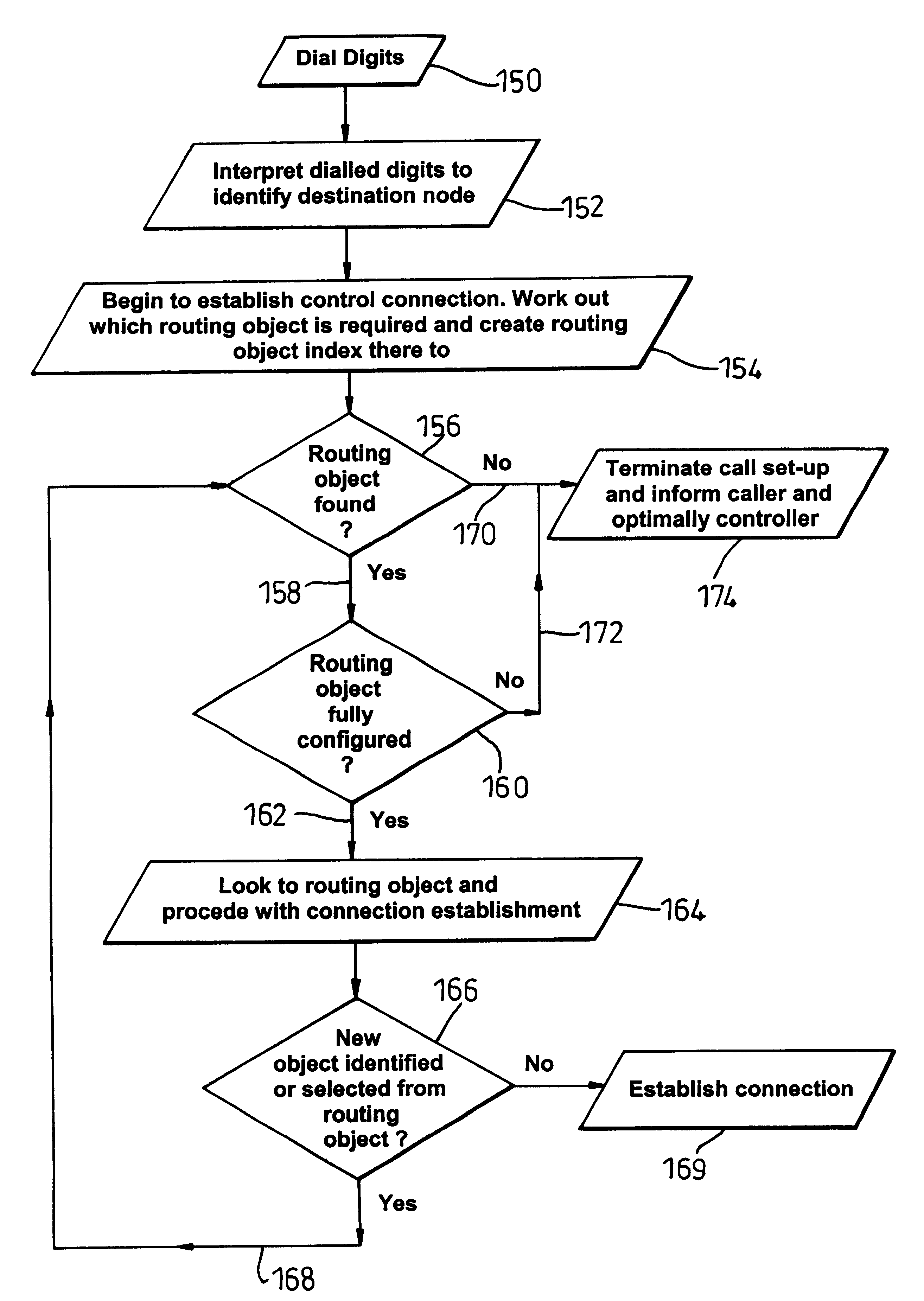
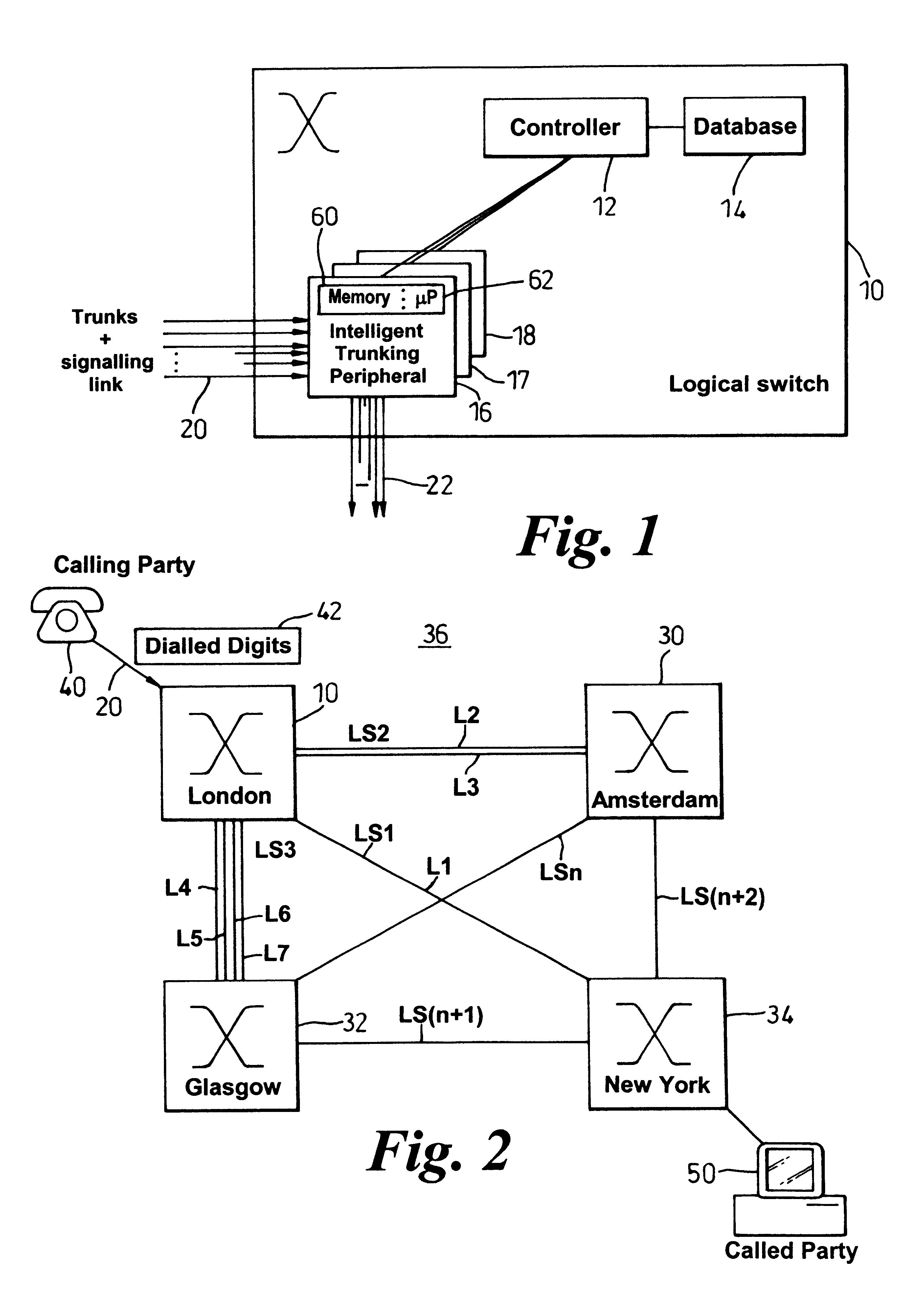
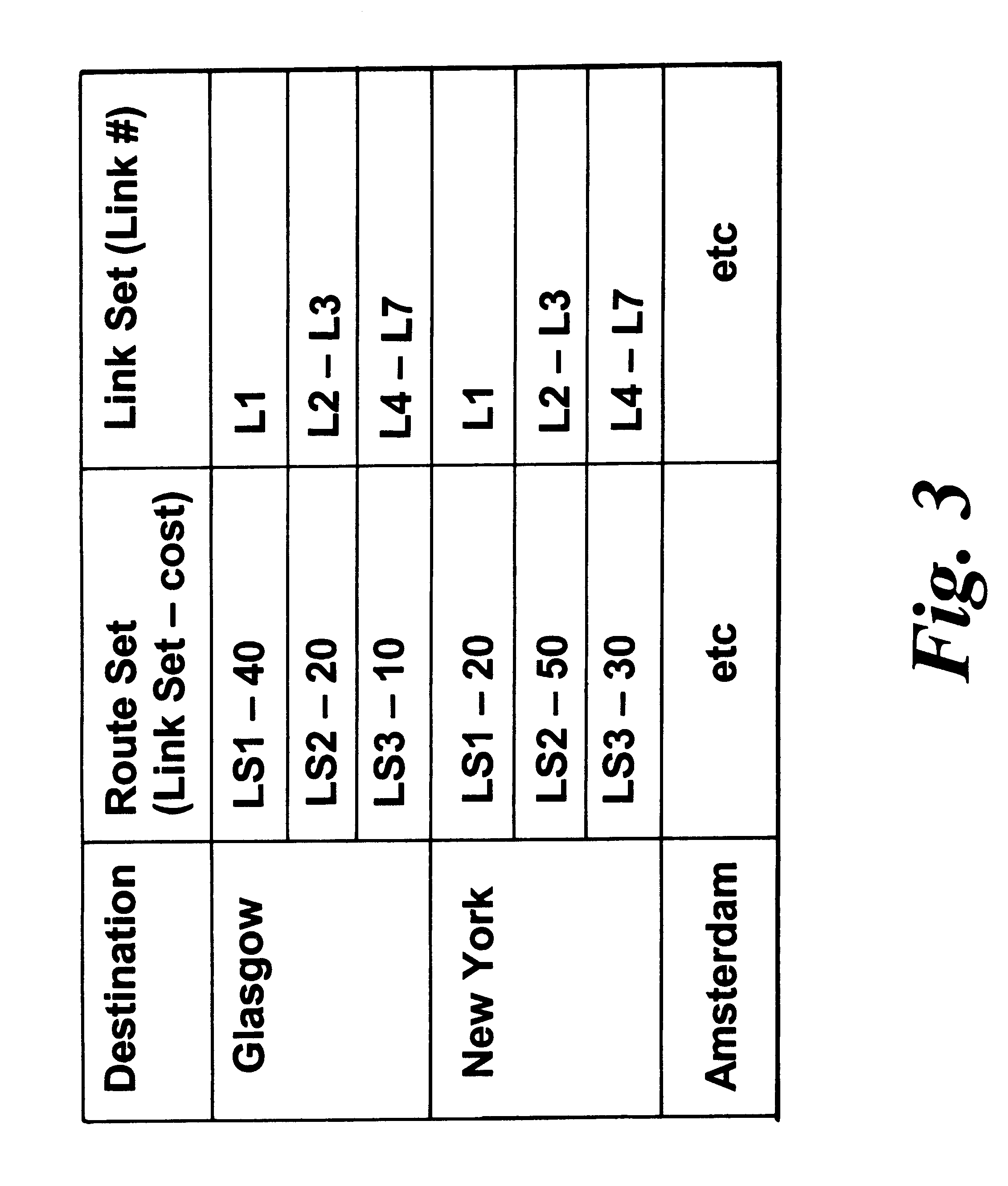
Turning briefly to FIGS. 1 to 3, a typical network architecture and connection topology is shown, which architecture and topology can capable of supporting the concepts of the present invention. Basically, a node (e.g. a logical switch) 10 is shown to contain a controller 12 and associated database 14. The controller is coupled to a plurality of intelligent trunking peripherals 16-18 which themselves terminate incident trunks 20. Communication links 22 provide for interconnection of the node 10 to other nodes 30-34 within the network 36.

The function of equipment within the system and the inter-operation and set up of a call has already been described in considerable detail above, and so for the sake of brevity more elaborate description at this point is superfluous. It is suffice to say that FIG. 2 shows a calling party 40 that has accessed an intelligent trunking peripheral 16 via dialled digits 42 sent over a communication resource, e.g. one of the plurality of incident trunks 20....


PUM


Abstract

To avoid searching for objects that are not effectively configured and therefore to mitigate connectivity and system failure, an intermediate routing object index (100, 103) is created to each and every object in a system (36). In a telecommunications system, for example, an object is only operational at a node (10, 30-34), such as a switch, upon receipt of all necessary configuration messages (102) from an overall system controller (12) responsible for overseeing operation of the node (10, 30-34) and the set-up of a connection. The routing object index stores (103, 108) an indication of the receipt of the necessary configuration messages and so provides a direct indication of whether the object exists and whether it is effectively configured. Consequently, during a connection establishment process in which control information, such as dialled digits (42, 150), indicates a called party (50) and more especially its serving node (34), the system of the present invention initially creates (100) and then subsequently accesses (156) the routing object index before attempting to locate the associated object (164). Should the routing object index fail to provide verification (106, 172) of a fully configured object or if the routing object does not exist (170), the routing object index causes the system to indicate (174) that a connection is not presently possible. The routing object index can also provide a mechanism for tracking (114-118) system configuration at a node level.

Description

BACKGROUND TO THE INVENTIONThis invention relates, in general, to a method of configuring a system and a method of establishing a connection in such a system. More particularly, but not exclusively, the present invention relates to a communication system that utilises object-orientated code to construct a routing matrix used to establish a connection in a telephony system, such as a mixed broadband-narrowband network.SUMMARY OF THE PRIOR ARTTelecommunication networks comprise nodes interconnected by communication resources (usually termed "links"), with a particular network technology characterised by the means of transmission of user and control information along these links and also by the routing and relaying functions embodied in the nodes. A connection from a calling party to a called party is actually achieved through an appropriate selection of a communication path, which path is determined on the basis of several decisions made by routing logic contained within switch fabric...

Claims


Application Information

Patent Timeline
Patent Type & Authority Patents(United States)
IPC IPC(8): H04Q3/64H04Q3/66
CPCH04Q3/66H04Q2213/1307H04Q2213/13103H04Q2213/13106H04Q2213/13109H04Q2213/13141H04Q2213/13148H04Q2213/13353Y10S370/904
Inventor SCOTT, BARRYBAILEY, STUART S
Owner RPX CLEARINGHOUSE
Why Eureka
Try Eureka