Meshing slide fastener with an engaging device

a technology of engaging device and sliding fastener, which is applied in the can solve the problems of limited use field of sliding fasteners of meshing type, and inability to achieve smooth separation or meshing operation

Inactive Publication Date: 2003-01-28
YKK CORP
View PDF18 Cites 24 Cited by
  • Summary
  • Abstract
  • Description
  • Claims
  • Application Information

AI Technical Summary

Problems solved by technology

Therefore, there is a problem that its usage field is limited, so that this meshing type slide fastener cannot be used for clothes which is to be separated to right and left sections to be opened completely.
However, an operation for separating the right and left meshing rows 1", 2" is very complicated, so that smooth separation or meshing operation can not be achieved.
Therefore, this meshing type slide fastener is far from being practical.

Method used


Image

  • Meshing slide fastener with an engaging device
  • Meshing slide fastener with an engaging device
  • Meshing slide fastener with an engaging device

Examples


first embodiment

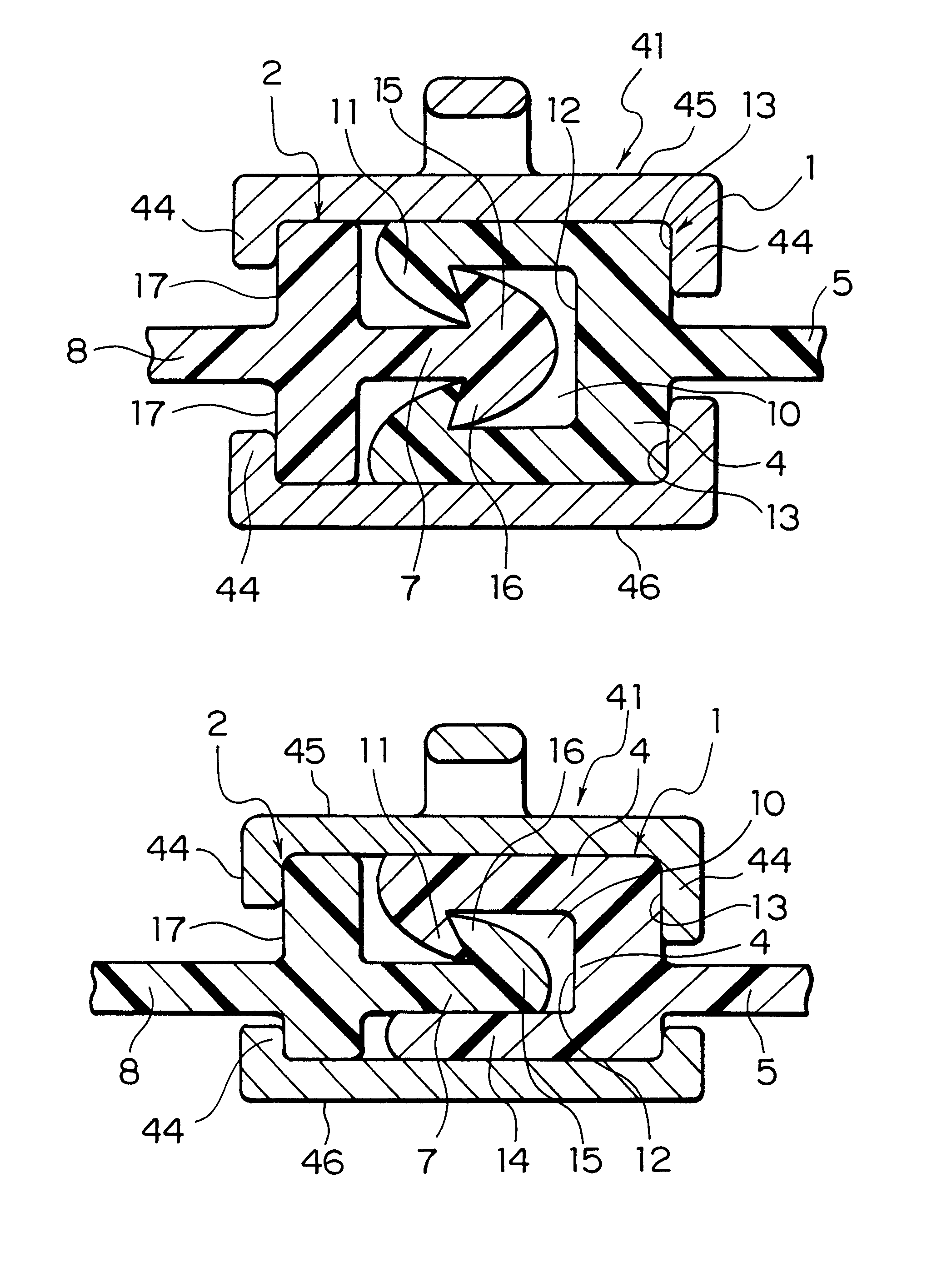
According to the meshing type fastener chain, as shown in FIG. 1, the concave row 1 has a concave-row-meshing portion 4 formed with a pair of hook-shaped engaging pieces 11 whose front ends are directed inward so as to oppose each other. A fitting concave portion 10 is formed between both the engaging pieces 11 for engaging with the convex-row-meshing portion 7. A flat concave-row-supporting portion 5 is provided laterally on part of an outside of a bottom portion 12 of the fitting concave portion 10, for example, in a central portion thereof, so that a pair of slider guide portions 13 for guiding a slider 41 are formed on faces of the bottom portion 12 above and below the concave-row-supporting portion 5.

On the other hand, as shown in FIG. 1, the convex row 2 for meshing with the concave row 1 has a convex-row-meshing portion 7 formed with an engaging head 15 having a mushroom shaped section, which has engaging portions 16 at both front and rear sides of an end of the convex row 2....

second embodiment

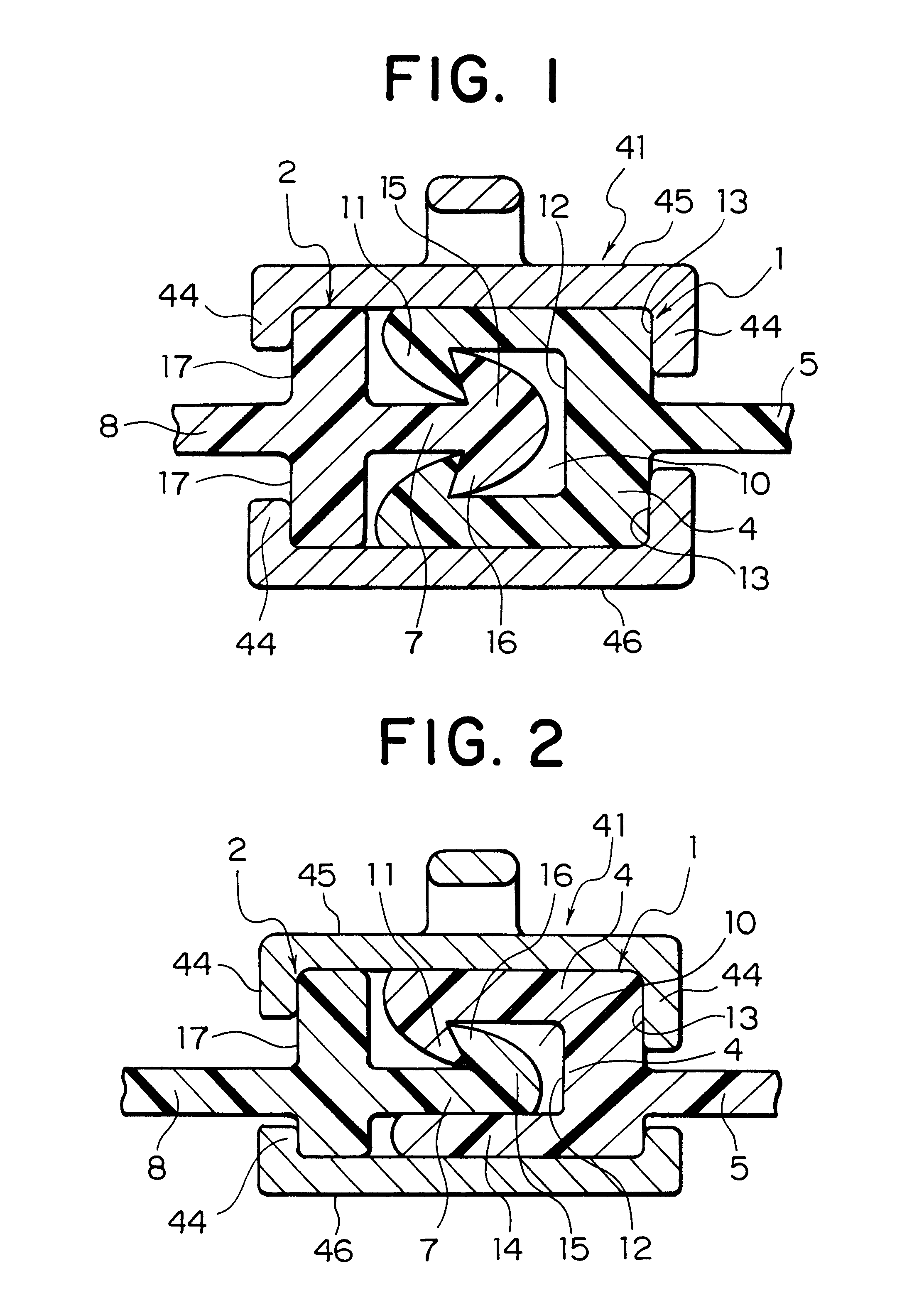
the meshing type fastener chain will now be described. As shown in FIG. 2, a concave row 1 has a hook-shaped engaging piece 11 whose top end is bent inward, at one side edge thereof, while the other opposing side edge is formed in a shape of a flat tongue-like portion 14 so as to oppose the engaging piece 11. A concave-row-meshing portion 4 is formed with a fitting concave portion 10 capable of fitting to a convex-row-meshing portion 7 between the engaging piece 11 and a tongue piece 14. A flat concave-row-supporting portion 5 is provided laterally on part of the outside of a bottom portion 12 of the fitting concave portion 10, for example, on a portion lower than the central portion thereof, so that slider guide portions 13 for guiding a slider 41 are formed on faces above and below the concave-row-supporting portion 5.

A convex row 2 has, as shown in FIG. 2, a convex-row-meshing portion 7 formed with a hook-shaped engaging portion 16 having an engaging head 15, whose tip end is dir...


PUM


Abstract

A concave row and a convex row of a meshing slide fastener are molded of resin having plasticity. The convex row has a terminal end where slider guide portions for guiding a slider are removed. A convex-row-meshing portion of the convex row is inserted through a side of the slider so as to be engaged with a concave-row-meshing portion of the concave row. An engaging device including a female fastening member and a male fastening member is attached to terminal ends of the concave row and the convex row. In operation, the female fastening member of the engaging device on a side of the convex row is engaged with the male fastening member of the engaging device on the side of the concave row. After the slider is made to contact with the engaging device on the side of the concave row, the convex row is rotated with respect to the female fastening member and the male fastening member and inserted between guide flanges of the slider, so that the concave-row-meshing portion and the convex-row-meshing portion are meshed with each other by sliding of the slider. By conducting an inverse operation, the meshing is released so that the concave row and the convex row are separated from each other. Therefore, the meshing slide fastener with an engaging device can be meshed with and separated from each other by a simple operation.

Description

1. Field of the InventionThe present invention relates to a slide fastener with water / air tightness, having a pair of concave row convex rows formed of thermoplastic resin adapted to mesh with each other, which is generally called a rail-shaped fastener. More particularly, it relates to a meshing type slide fastener, wherein an engaging device or an opening device is provided at the respective end portions of the concave row and the convex row so as to enable right and left parts thereof to be separated, and by engagement of the engaging device and sliding of a slider, the concave row and the convex row can be meshed with each other.2. Description of the Related ArtFIG. 14 shows a conventional slide fastener having a pair of concave and convex rows 1', 2' made of thermoplastic resin, which is disclosed in Japanese Utility Model Publication No. 48-36003. As shown in FIG. 14, in the slide fastener, end portions of the pair of meshing concave row 1' and convex row 2' disposed on the ri...

Claims


Application Information

Patent Timeline
Patent Type & Authority Patents(United States)
IPC IPC(8): A44B19/24A44B19/38A44B19/16A44B19/32
CPCA44B19/388Y10T24/2593Y10T24/2534Y10T24/2532A44B19/02
Inventor MATSUSHIMA, HIDEYUKIMORI, HIROSHI
Owner YKK CORP
Why Eureka
Try Eureka