Safety support with a noise attenuator for a vehicle wheel

a technology of safety support and vehicle wheel, which is applied in the direction of inflatable tyres, tyre beads, transportation and packaging, etc., can solve the problems of supplementary costs, material and manufacturing time, and adding an additional mass

Inactive Publication Date: 2003-02-11
MICHELIN RECH & TECH SA
View PDF13 Cites 52 Cited by
  • Summary
  • Abstract
  • Description
  • Claims
  • Application Information

AI Technical Summary

Benefits of technology

This arrangement, in which the support forms at least one of the walls of a resonator, permits the attenuation of the amplitude, or even the suppression, of one or more natural resonances of the cavity, in particular of the first cavity mode. Each resonator, which is placed so as to communicate with the cavity C, tuned to the frequency or the range of frequencies on which it is desired to act, permits dissipation of the vibrational energy. It is thus possible to minimize or eliminate the transfer of vibration or sound to the passenger compartment via the wheel.
According to this particularly advantageous embodiment of the invention, a support of known type is used, comprising a series of circumferentially aligned cavities, but with one side open, to which simply a wall which makes it possible to close these cavities is added, in order to form the cavity of the resonator(s). In order to simplify the arrangement, the openings are provided in the attached wall. This involves a minimal modification of the support, since merely a complementary element is added thereto. It therefore retains substantially the same mass. The costs inherent in such a modification are furthermore minimal.

Problems solved by technology

For example, the first cavity mode (sometimes referred to as FCM) is a well-known phenomenon, but the attenuation or suppression thereof always causes numerous difficulties.
It is therefore an additional piece, which requires material and manufacturing time, hence supplementary costs, on the one hand, and adding an additional mass to the wheel, on the other hand.

Method used


Image

  • Safety support with a noise attenuator for a vehicle wheel
  • Safety support with a noise attenuator for a vehicle wheel
  • Safety support with a noise attenuator for a vehicle wheel

Examples


Embodiment Construction

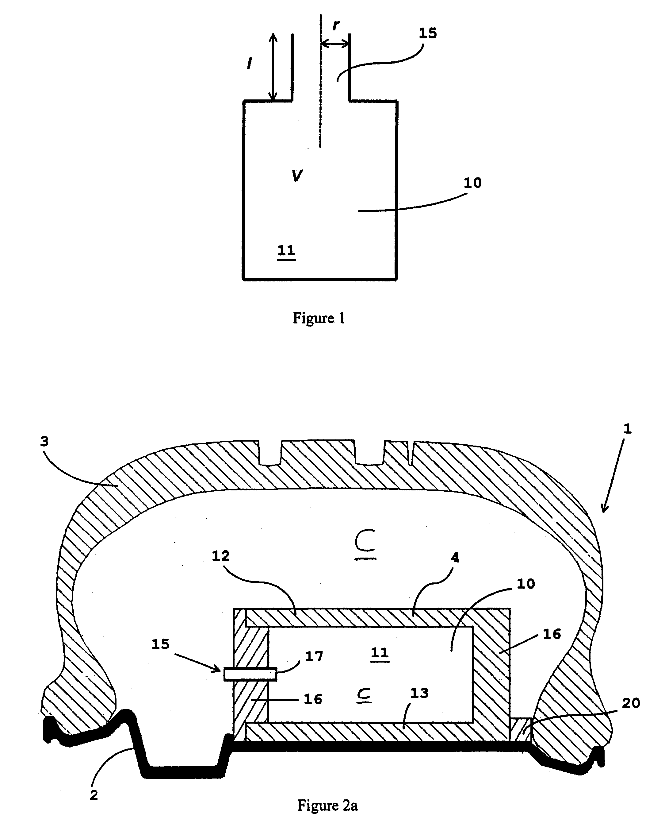
FIG. 1 illustrates diagrammatically the principle of operation of a Helmholtz resonator 10. Such a resonator includes a cavity 11, defining a volume V and having an opening or neck 15 of radius r (or section a) and of length 1. This arrangement provides a mode of vibration at a given frequency. It is in fact the volume of air, or of a given gas, contained in the neck 15 which is caused to move in an oscillating movement. It may be likened to a small mass; the cavity of the resonator then acts as a spring on which the mass bears. In the case in which the opening of the cavity is circular, the frequency of this resonator is provided by the following relationship:

f.sub.H (k / 2.pi.)X(a / l'V).sup.1 / 2 (1)

The frequency, therefore, depends only on the speed of the sound k and the dimensions of the resonator.

In Equation (1), 1' is the apparent length of the neck of the resonator. For a cylindrical neck of radius r (section a=.pi.r.sup.2), this apparent length is calculated as follows:

l'=1+1.5 ...


PUM


Abstract

A vehicle wheel, comprising a rim, a disc, a tire defining with the rim a circumferential cavity C, and at least one resonator suitable for attenuating a natural resonant frequency of said cavity, said wheel also comprising a safety support, for supporting the tread of this tire from the inside in the event of loss of inflation pressure, said support providing at least one of the walls of said resonator. The invention also provides for the safety support comprising resonators.

Description

BACKGROUND OF INVENTION1. Technical Field of the InventionThe present invention relates to a safety support for a vehicle wheel with a tire, comprising at least one noise attenuator of the Helmholtz resonator type or the quarter-wave resonator type.2. The Related ArtsSafety supports for vehicle wheels which use a tire are well-known. Document EP 0 796 747 describes an example of such a support. It consists of a circular body suitable for mounting on the rim of a vehicle. The example illustrated in this document is formed primarily of a vulcanised rubber mix, some zones of which are reinforced, for example with metal- or textile-type filaments. Of course, other materials may be used to produce such a support.Generally, safety supports are mounted on a rim, within a tire, in order to provide a support for the crown of the tire during travel at low pressure, or even at zero pressure, following a puncture, for example. Thus, direct contact between the tire and the rim, which generally c...

Claims


Application Information

Patent Timeline
Patent Type & Authority Patents(United States)
IPC IPC(8): B60C15/02B60C19/00B60C17/00B60C17/04B60C15/00B60C5/00B60B21/12
CPCB60C3/06B60C19/002B60C17/04B60C15/0236B60C17/061
Inventor FLAMENT, JULIENJUBERT, DENIS
Owner MICHELIN RECH & TECH SA
Why Eureka
Try Eureka