Slip control system of torque converter

a control system and torque converter technology, applied in fluid gearings, transportation and packaging, gearing, etc., can solve the problems of generating shocks and residual noise, slip control systems of these publications have not shown a satisfied performance in slip rotation control, etc., to achieve the effect of reducing the range of vehicle speed and reducing the fluctuation of minimum torque and toque multiplier functions

Inactive Publication Date: 2003-05-20
NISSAN MOTOR CO LTD
View PDF7 Cites 46 Cited by
  • Summary
  • Abstract
  • Description
  • Claims
  • Application Information

AI Technical Summary

Benefits of technology

In order to solve the above-mentioned problem, various slip control systems for the torque converter have been hitherto proposed. One of them is of a system wherein a slip control range is so set that with the lock-up clutch being left in a so-called half-engaged condition (viz., slip control condition), the slip rotation of the torque converter is so controlled or restricted as to assure the minimum torque fluctuation absorbing and toque multiplying functions. With this, the slip rotation control can be effected at a much lower vehicle speed range.
In general, in the above-mentioned slip control system, a target slip rotation speed is determined in accordance with vehicle operation factors, such as engine throttle opening, vehicle speed, temperature of hydraulic fluid of the transmission, etc., and the engaging force of the lock-up clutch is so controlled that, in the above-mentioned slip control range, the real slip rotation speed is finally controlled or converged to the target slip rotation speed. According to the above-mentioned slip control system, from a theoretical point of view, the slip rotation control can be extended to much lower speed range without suffering from residual noises and shocks and thus improvement in fuel consumption is achieved avoiding deterioration of drivability of the vehicle.

Problems solved by technology

However, in fact, since the engaging force of the lock-up clutch for controlling the slip rotation speed can not be theoretically controlled, shocks and residual noises tend to be produced due to a temporary engagement of the lock-up clutch.
However, as will be described hereinafter, even the slip control systems of these publications have failed to exhibit a satisfied performance in the slip rotation control.

Method used


Image

  • Slip control system of torque converter
  • Slip control system of torque converter
  • Slip control system of torque converter

Examples


Embodiment Construction

In order to assist understanding of the present invention, the slip control systems proposed by the above-mentioned two Japanese Patent Publications will be analyzed before making a detailed description on a slip control system of the present invention.

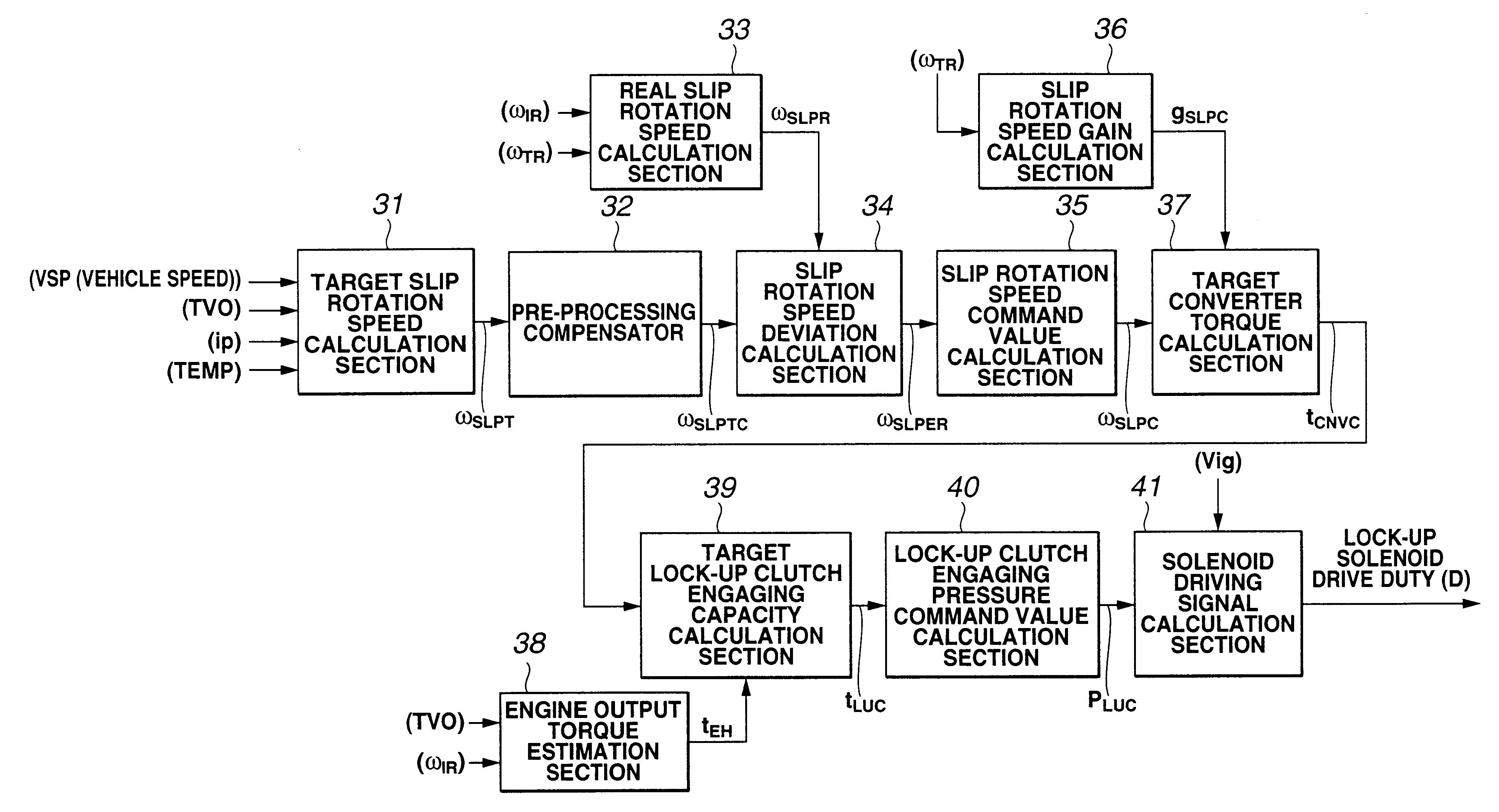
The slip control system shown in the publication 11-82726 is based on an understanding wherein, under a slip control condition of the torque converter, the input torque of the converter (viz., engine output torque) corresponds to the sum of the converter torque by the hydraulic transmission of the converter and the engaging capacity of the lock-up clutch. Based on a certain relation between the converter torque and the slip rotation speed that is previously derived from the transmission performance of the torque converter, a target converter torque is calculated, which is needed for obtaining a slip rotation command value for converging the real slip rotation speed to the target slip rotation speed. By subtracting the target converter...


PUM


Abstract

A controller of a slip control system of a torque converter with a lock-up clutch is configured to carry out calculating a target slip rotation speed of the converter based on a vehicle speed and an open degree of a throttle valve; calculating a running condition of the vehicle, which includes drive and coast conditions, based on the operation condition of the throttle valve; calculating a torque converter characteristic with reference to a speed of a turbine of the converter and the running condition of the vehicle; calculating a target converter torque based on the torque converter characteristic; calculating a target lock-up clutch engaging torque based on the target converter torque and an engine torque; and outputting an instruction signal to an actuator to provide the lock-up clutch with the target lock-up clutch engaging torque. The torque converter characteristic is represented by two groups of maps, one being for the drive running condition and other being for the coast running condition.

Description

BACKGROUND OF INVENTION1. Field of InventionThe present invention relates in general to control systems for controlling a torque converter used with an automatic transmission and more particularly to control systems of a type that controls a relative rotation (or slip rotation) between input and output elements of the torque converter. More specifically, the present invention is concerned with a slip control system for converging the slip rotation of the torque converter to a target level.2. Description of Related ArtThe torque converter is a device that carries out a power transmission between input and output elements through a fluid. Thus, the torque converter is somewhat poor in having a satisfied power transmission efficiency although it exhibits a good torque fluctuation absorbing function and a good torque multiplying function.Accordingly, nowadays, a so-called lock-up type torque converter has been widely used, which, under a vehicle running condition wherein the torque fluc...

Claims


Application Information

Patent Timeline
Patent Type & Authority Patents(United States)
IPC IPC(8): F16H61/14
CPCF16H61/143Y10T477/755Y10T477/75F16H2061/145
Inventor SEGAWA, SATOSHIADACHI, KAZUTAKA
Owner NISSAN MOTOR CO LTD
Why Eureka
Try Eureka