Golf club head construction

a golf club and head technology, applied in golf clubs, golf, sport apparatus, etc., can solve the problems of infinite number of bad lie possibilities and poorer standard club achievement prospects

Inactive Publication Date: 2004-08-24
HERBER PAUL J
View PDF31 Cites 31 Cited by
  • Summary
  • Abstract
  • Description
  • Claims
  • Application Information

AI Technical Summary

Problems solved by technology

Also, according to the rules of golf the ball is played where it lies (i.e., where it was hit to) and cannot usually be moved to improve the lie without penalty.
Moreover, the longer the desired flight for the ball being struck in a bad lie, the poorer the prospects of achievement with standard clubs especially when using the longer fairway woods (e.g., numbers 3, 4 and 5 woods).
Although the number of bad lie possibilities is practically infinite, a usual bad lie encountered by a player at least once per round, is to find the ball buried down within grass and still have a long way to the green.

Method used


Image

  • Golf club head construction
  • Golf club head construction
  • Golf club head construction

Examples


Embodiment Construction

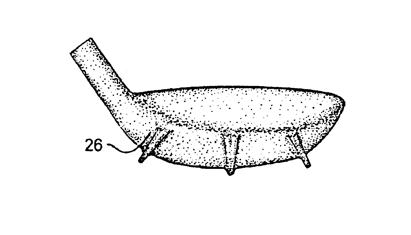
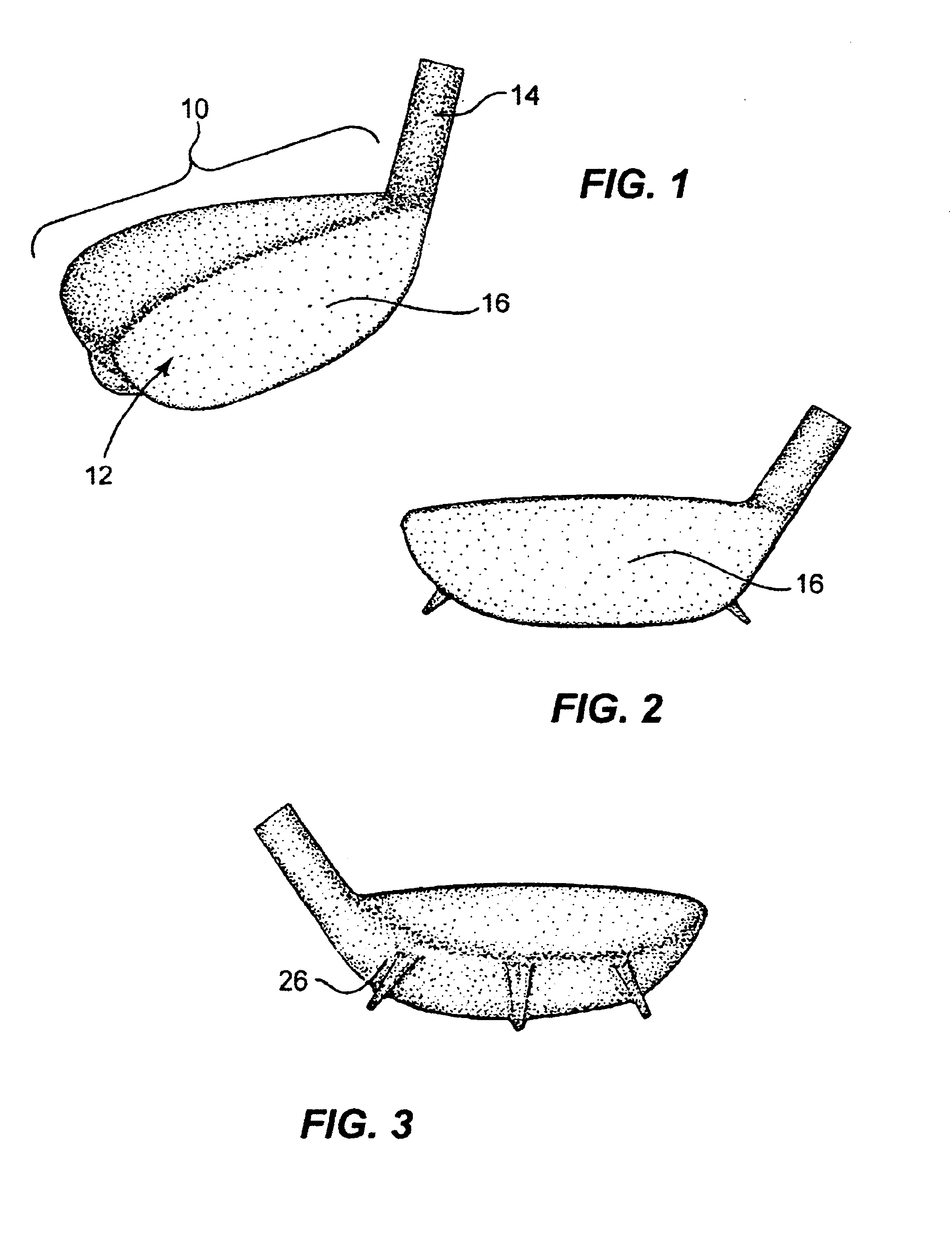
For the ensuing description of the invention reference is now made tp the drawings. In its major aspects, the club head 10 of the invention is of the so-called "wood" category having a head portion 12 with a unitary hosel 14 for connection, in turn, to a club shaft (not shown). The head portion 12 has ball striking surface 16 and a bottom surface 18 adapted for resting or near-resting deployment with the ground when preparing to strike a ball. As described to this point, the head portion and attached hosel are of conventional construction and although referred to as a "wood" club, they are presently usually made of metal and for that reason are frequently referred as a "metal woods".

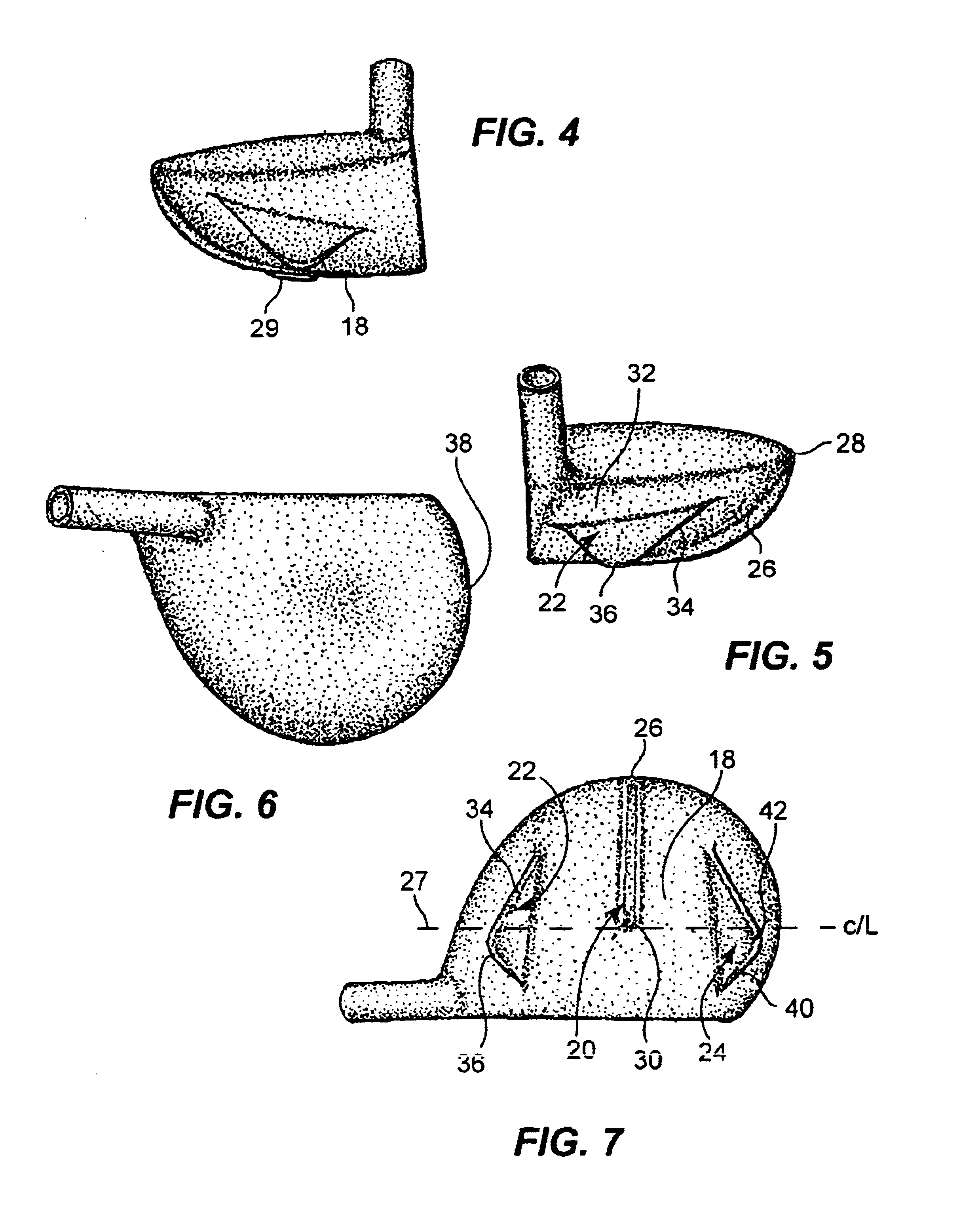
With reference now to FIGS. 2, 3, 4, 5 and 7, it is seen that first, second and third guide fins 20, 22 and 24 are integral with the bottom and upwardly sloping side walls of the head portion as will be more particularly described. The first guide fin 20 is generally flat and planar with an edge continuo...


PUM


Abstract

A golf club head (10) of the wood variety includes a first, second and third spaced apart guide fins (20, 22, 24) arranged from the hosel end of the head portion (12) to the opposite tip end. The first fin (20) extending along the lower and rear surfaces of the head portion is orthogonal to the ball striking surface (16). The second fin (22) on the hosel curved end wall extends angularly toward the player and angularly to the first fin. The third fin (24) is located on the tip (38) end wall extending downwardly and outwardly from the head portion. All three fins have respective maximum extension points (30, 36, 42) such that the club head can rest on these points on a flat surface spacing the major lower head portion surface from flat surface.

Description

1. Field of the InventionThe present invention relates generally to a golf club head, and, more particularly, to a golf club head of the so-called "wood" variety providing improved ball striking prospects over a wide range of ball lie situations.2. Description of Related ArtIn the game of golf, the ball typically is hit on each hole onto the fairway (closely clipped grass) or into what is termed the "rough" adjacent the fairway where the grass is longer and may be mixed with all sorts weeds, rocks and other foreign objects. Also, according to the rules of golf the ball is played where it lies (i.e., where it was hit to) and cannot usually be moved to improve the lie without penalty. Still further, the slope of the ground can be found to vary considerably from one location to another even though the locations are quite close to each other. All of these various factors, taken individually or collectively, can make any given ball lie difficult to be reliably struck with a golf club so ...

Claims


Application Information

Patent Timeline
Patent Type & Authority Patents(United States)
IPC IPC(8): A63B53/04A63B69/36
CPCA63B53/0466A63B2225/01A63B2053/0433A63B53/0433A63B53/04
Inventor HERBER, PAUL J.
Owner HERBER PAUL J
Why Eureka
Try Eureka