Wiper blade with wiper strip to carrier element attachment means

a technology of carrier element and wiper strip, which is applied in the field of wiper blades, can solve the problems of inability to design the height of the wiping field determined by the length of the wiper strip to the maximum, and the carrier element spring properties are advantageously changed in terms of the intended wiping, etc., to achieve the effect of reliable anchoring of the wiper strip in the carrier elemen

Inactive Publication Date: 2005-01-04
ROBERT BOSCH GMBH
View PDF25 Cites 64 Cited by
  • Summary
  • Abstract
  • Description
  • Claims
  • Application Information

AI Technical Summary

Benefits of technology

Problem-free installation of the wiper blade is guaranteed when the means of attachment can be brought into their securing position after the wiper strip is positioned in the carrier element.
A stable and permanent anchoring of the wiper strip in the carrier element is achieved when the transverse ribs as well as the extension designed in the shape of a tongue connected as a single part to one of the transverse ribs are made out of metal.

Problems solved by technology

However, this act of expansion can disadvantageously change the spring properties of the carrier element in terms of the intended wiping results.
Additionally, it is cost-intensive to manually insert the wiper strip in the slit by way of this expansion.
As a result, the height of the wiping field determined by the length of the wiper strip cannot always be designed to the maximum, because the transverse ribs extending beyond the ends of the wiper strip must be taken into account.

Method used


Image

  • Wiper blade with wiper strip to carrier element attachment means
  • Wiper blade with wiper strip to carrier element attachment means
  • Wiper blade with wiper strip to carrier element attachment means

Examples


first embodiment

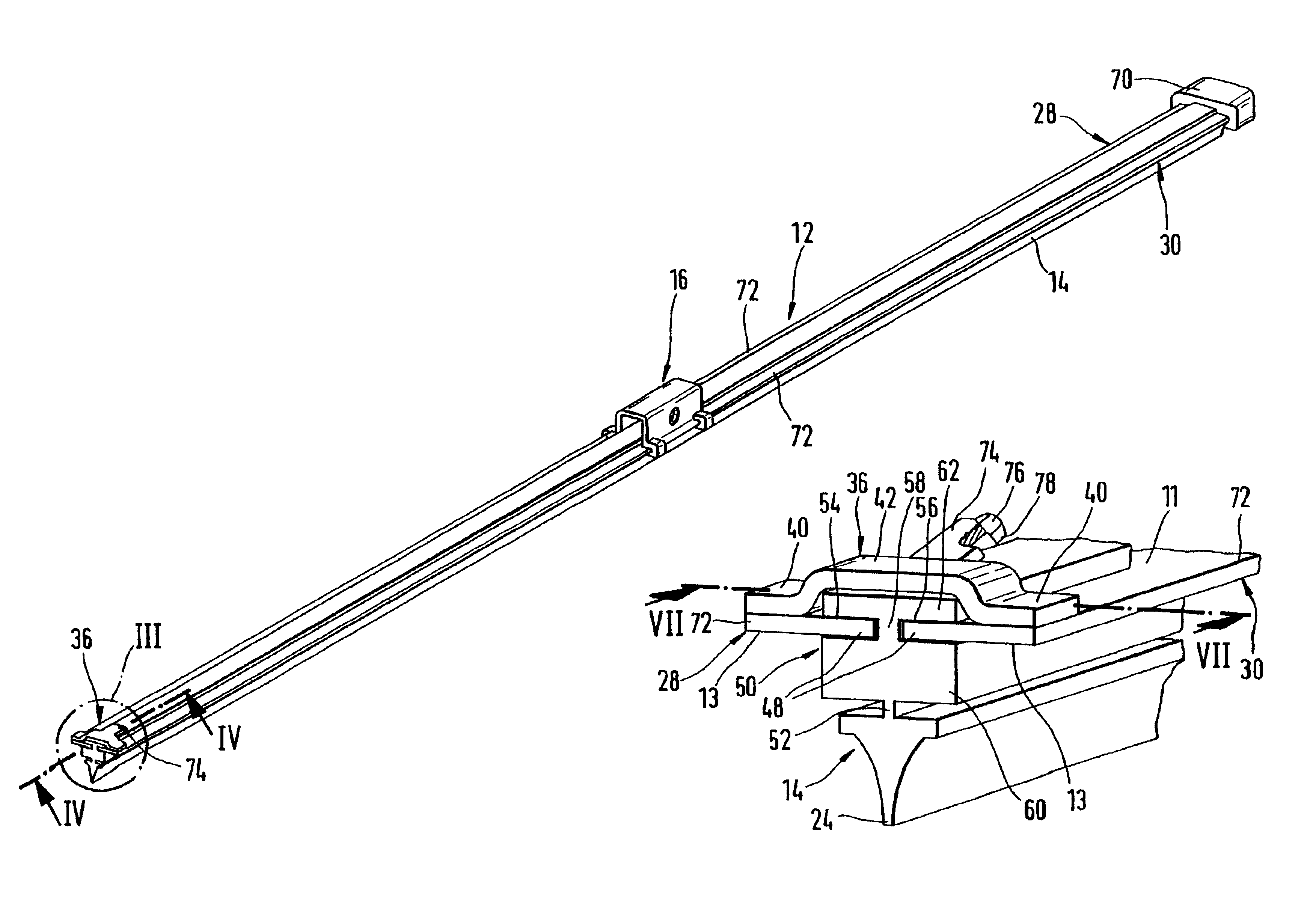
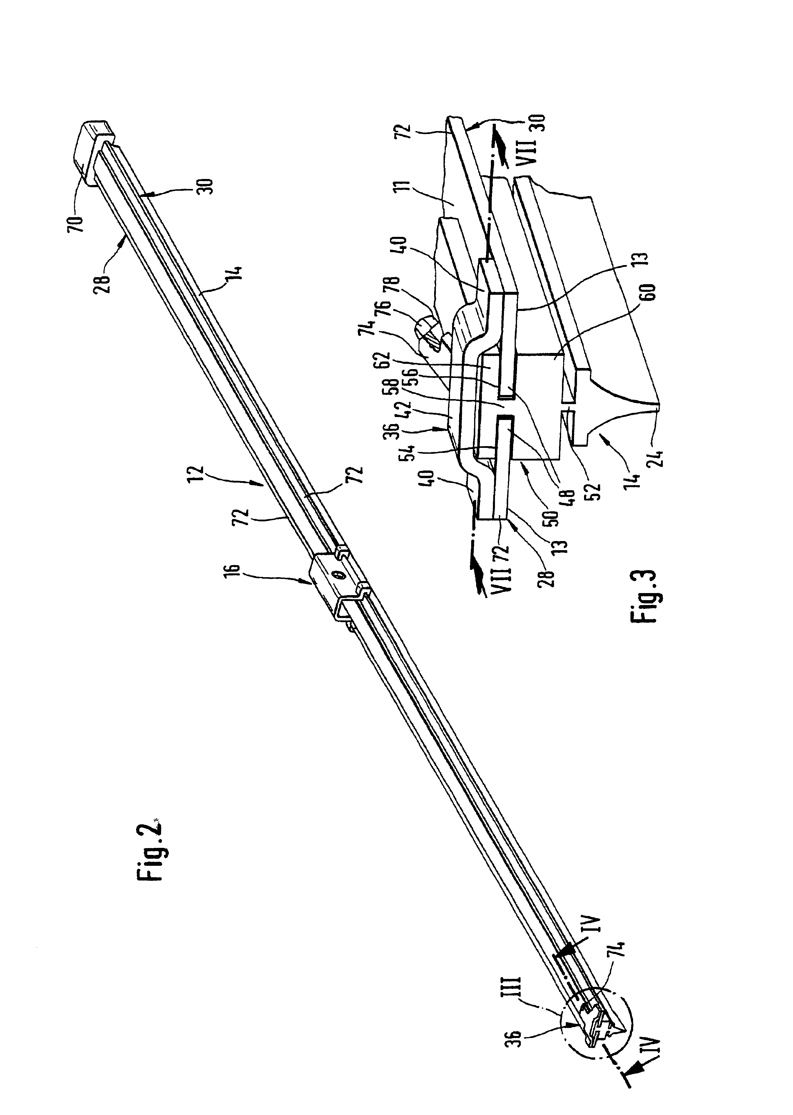
the wiper blade 10 shall be described below in greater detail using FIGS. 3 and 7. It is obvious in FIG. 7 that the carrier element 12 of the wiper blade 10 lies at a distance 26 in front of the window 22 to be wiped. Its arrangement is therefore selected so that its strap surfaces 11 and 13 are located in a plane that extends basically parallel to the window surface 22 to be wiped. The carrier element 12 has two springs 28 and 30 designed in the shape of a strap lying in a common plane parallel to each other. The inner longitudinal edges 32 facing each other are thereby located at a distance 34 from each other. They are connected to each other by way of a bridge-like transverse rib 36 on each of the two ends of the springs 28, 30; they are welded together, for example. Each bridge-like transverse rib thereby lies with both of its end sections 40 on the top 11 of the carrier element 12 and its springs 28, 30 (FIG. 5). Each of the two transverse ribs 36 has a center section 42 that i...


PUM


Abstract

A wiper blade (10) for windows, in particular of motor vehicles, is proposed that is equipped with a long, rubber-elastic wiper strip (14) that can be placed against the window (22), that is situated parallel to the longitudinal axis on a long, spring-elastic carrier element (12) to which a component (16) belonging to a device for attaching the wiper blade (10) to a driven wiper arm (18) is directly connected, whereby the carrier element (12) has springs (28, 30) designed in the shape of a strap lying in front of the window (22) in a plane that is basically parallel to the window, the bottom surfaces of the strap (13) of which face the window, the inner, adjacent longitudinal edges (32) of which have a distance between them and plunge individually into longitudinal grooves (54, 56) assigned to each longitudinal edge and open toward the longitudinal side of the wiper strip, and that are connected to each other by way of at least two transverse ribs (36) situated in the longitudinal direction with distance between them. A reliable and stressfree attachment of the wiper strip to the carrier element is insured when each transverse rib (36) has a center section (42) that extends at a distance from the top strap surfaces (11) of the springs (28, 30) so that bridge-like transverse ribs result, whereby the distance (34) between the two springs is less than the bridge width (46), and means of attachment (74, 76, 78) are situated on the carrier element (12) to secure the wiper strip (14) to the carrier element (12) in its longitudinal direction.

Description

BACKGROUND OF INVENTIONIn wiper blades of the type described according to the present invention, the carrier element is intended to insure the most even distribution possible of the wiper blade contact pressure against the window exerted by a wiper arm connected to the wiper blade over the entire wiping field covered by the wiper blade. Due to a corresponding curvature of the non-loaded carrier element—i.e., when the wiper blade does not lie against the window—the ends of the wiper strip lying fully against the window during the wiping operation of the wiper blade are loaded toward the window by way of the carrier element, which is then taut, even if the curvature radii of spherically curved motor vehicle windows change with each position of the wiper blade. The curvature the wiping blade must therefore be somewhat greater than the greatest curvature measured in the wiping field of the window to be wiped. The carrier element therefore replaces the expensive carrying strap constructi...

Claims


Application Information

Patent Timeline
Patent Type & Authority Patents(United States)
IPC IPC(8): B60S1/38
CPCB60S1/38B60S1/3879B60S2001/3822B60S2001/382B60S1/3893B60S1/32
Inventor DE BLOCK, PETERWIJNANTS, PETER
Owner ROBERT BOSCH GMBH
Why Eureka
Try Eureka