Microscope

a microscope and microscope technology, applied in the field of microscopes, can solve the problems of difficult use in extremely narrow portions, high cost of associated costs, and difficulty in observing the bottom part, so as to improve light efficiency.

US6853482B1Inactive Publication Date: 2005-02-08KITAMURA JUN +1
9 Cites 8 Cited by

Patent Information

Authority / Receiving Office
US · United States
Patent Type
Patents(United States)
Current Assignee / Owner
Publication Date
2005-02-08
Estimated Expiration
Not applicable · inactive patent

Smart Images

  • Figure 1
    Figure 1
  • Figure 2
    Figure 2
  • Figure 3
    Figure 3
Patent Text Reader

Abstract

The microscope (S, 100) of the present invention has a hand piece (20, 112), whose tip is mounted with a thin sheet-like mirror unit (M, 10, 130, 220), and around both ends of the base (11c, 131c) thereof is arranged an illuminating light source (32, 117), whereby light is emitted to a target object, image light is lead through the light reception bore (27, 116), to the optical system (114), and is recorded at the CCD camera (111), to obtain video images. The thin sheet-like mirror (M, 11, 131) confines light and navigate it, wherein the width of the mirror can be made narrower like a convergent taper surface (11a, 131a); and it is comprised of a base surface (11c, 131c) where illuminating light comes in and image light goes out, and a mirror surface (11b, 131b) where illuminating light and image light go back and forth, and make the reflection thereof, and the mirror surface (11b, 131b) is slanted to 45 degrees. The microscope may be used as a handy microscope if it is not equipped with a charge-coupled device camera. The microscope can provide a wider horizon, which makes it possible to make a horizontal observation in an extremely narrow space, and can be manufactured at a less expensive price.
Need to check novelty before this filing date? Find Prior Art

Description

TECHNICAL FIELDThe present invention relates to a microscope utilized as a probe for observing an extremely small portion or a microscopic construction of an object; for example, conditions of the BGA (Ball Grid Array), skin, etc. can be observed or examined.BACKGROUND TECHNOLOGIESWhen observing constructions of the skin, conditions of the hair, etc., hand-held microscopes have been frequently used in the fields of medicine, cosmetics, etc. recently, as well as applications of such microscopes have been under development in the field of the manufacturing industry for various machines, and electric and electronic products, or machines, electronic and electric parts to be used therewith.Among them, when illustrating an example in the case of an ultra-small package BGA soldering, the BGA of this type has come to be more and more frequently used in a wide variety of utilities, such as LSI's in mobile phones, digital camera built-is VTR's, high-performance microprocessors in mobile infor...

Examples

first embodiment

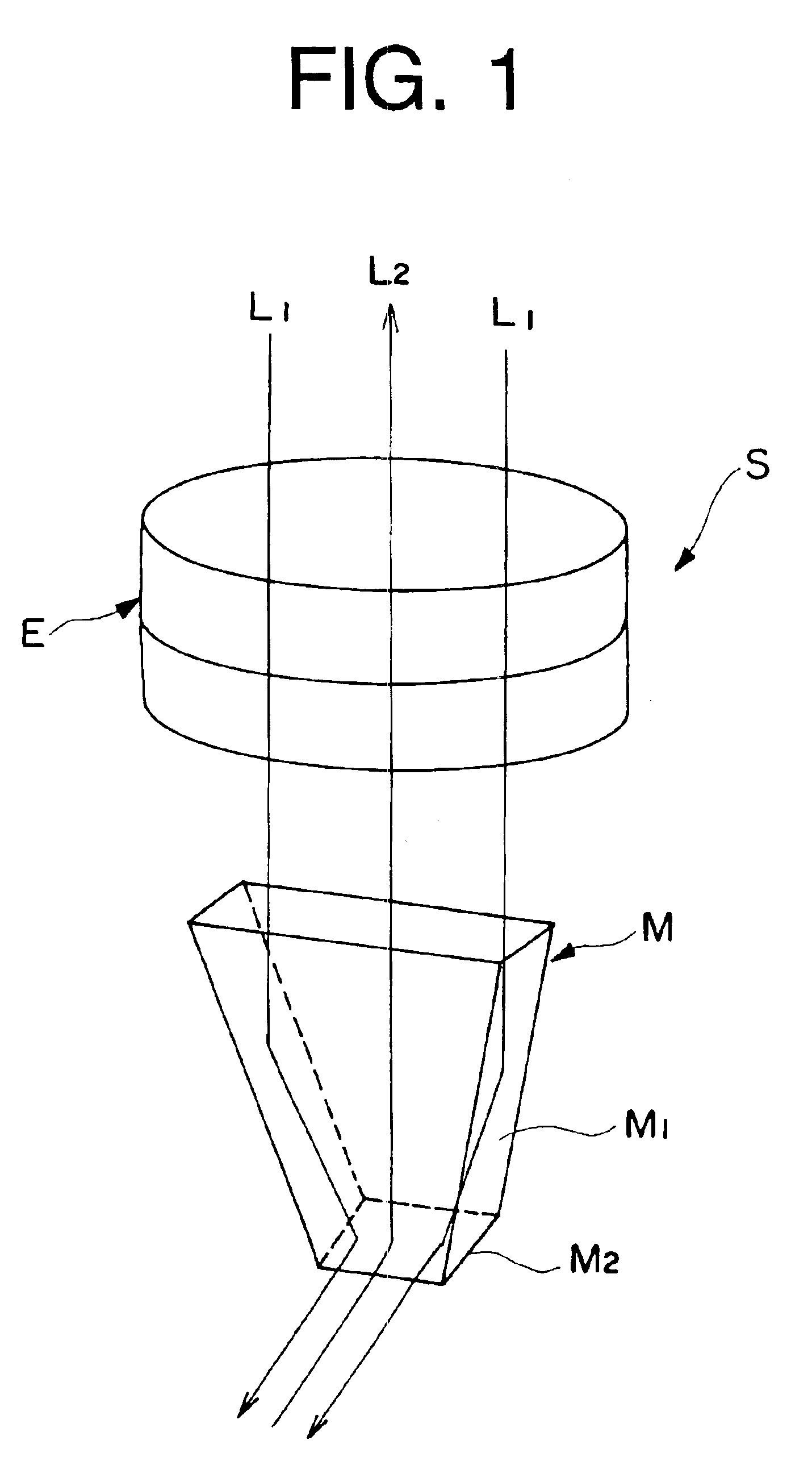
the present invention is a case where a microscope is used as a loupe, and FIG. 1 is a perspective view showing a principle structure of such a microscope, i.e., a loupe.

Namely, this microscope S is basically comprised of a magnifying lens E, and a thin sheet-like mirror M, wherein the thin sheet-like mirror M is constructed in such a way that the width of the tip end thereof becomes narrower, and is preferably formed as a convergent taper surface M1, and at the tip thereof there is provided a mirror surface M2 cut out at an acute angle.

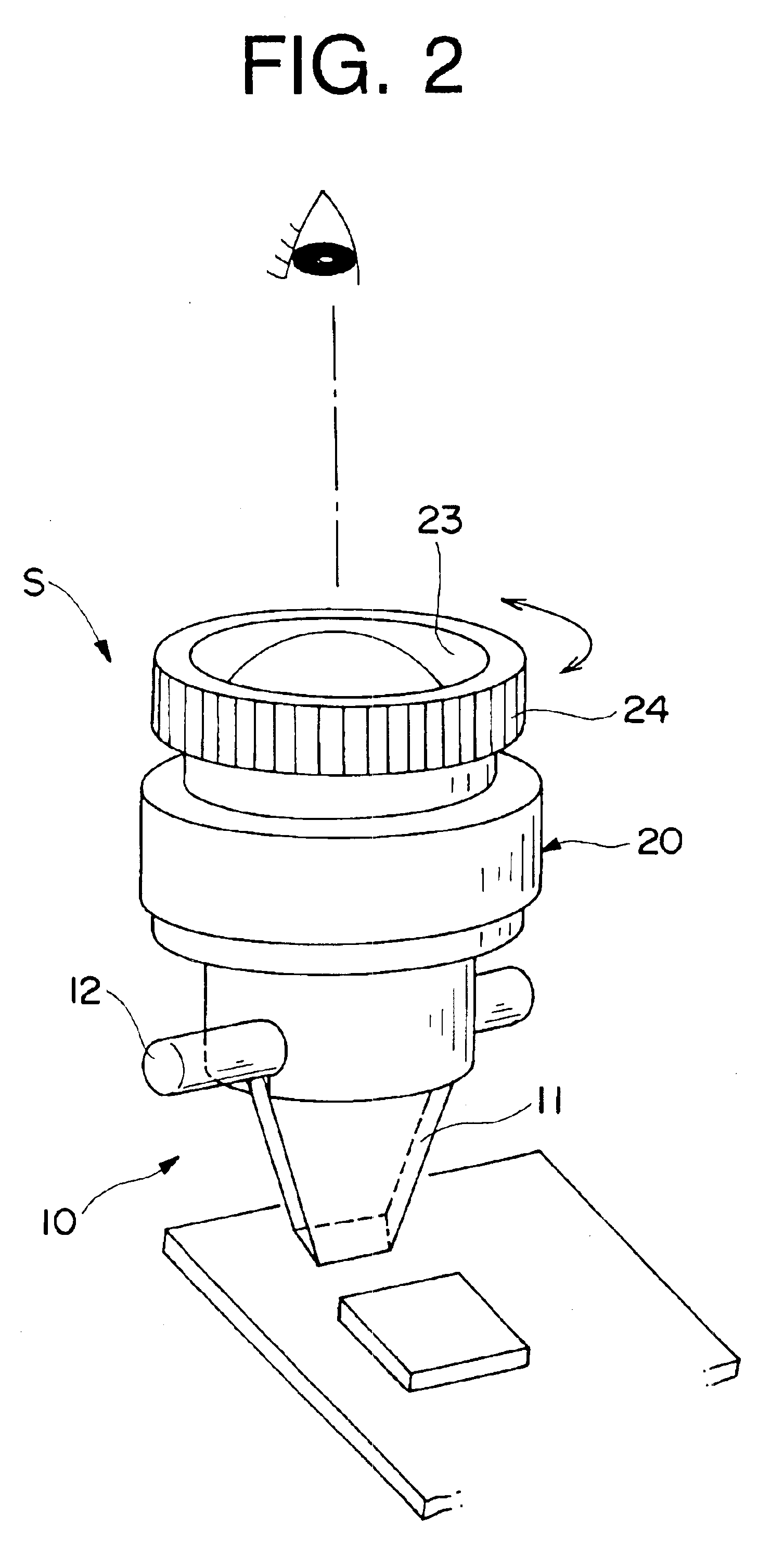
In FIG. 1, when making an observation from an eye lens that is not included in the figure by placing a target object near the mirror surface M2 of the microscope S, and put a loupe in an upright position, and through the mirror surface M2, the reflected image of the target object can be shown as a magnified image.

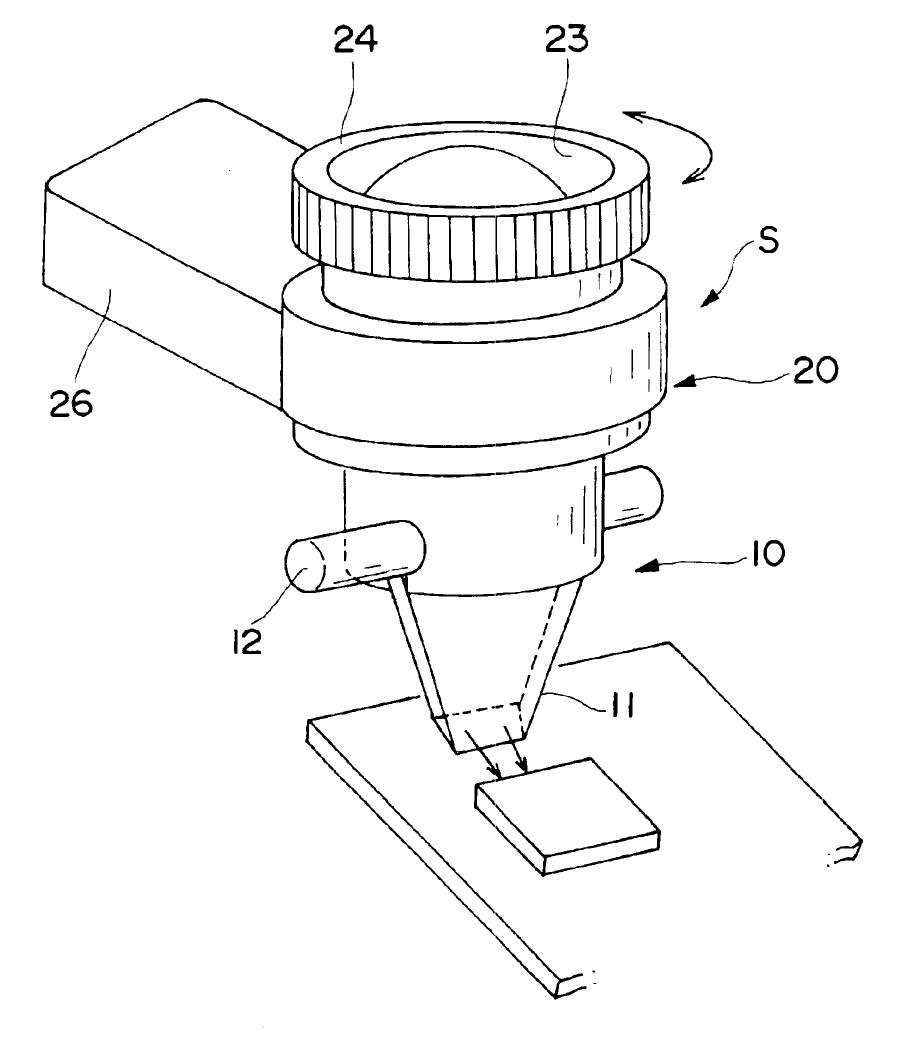
FIGS. 2 and 3 show application examples when the microscope is used as a loupe. The thin sheet-like mirror 11 mounted at the tip of this lo...