Locking device

a technology of locking device and locking ring, which is applied in the direction of wing knobs, vessel construction, transportation and packaging, etc., can solve the problems of bolt member and/or coaming damage,

Inactive Publication Date: 2005-02-15
SOUTHCO
View PDF12 Cites 14 Cited by
  • Summary
  • Abstract
  • Description
  • Claims
  • Application Information

AI Technical Summary

Benefits of technology

According to the present invention there is provided a locking device including a handle member, a rotatable member connected to the handle member, and a bolt member connected to the rotatable member so as to follow rotational movements of the handle between a ...

Problems solved by technology

In an open position of the hatch, it may inadvertently occur that the locking device is in a position where the bolt member projects more or less beyon...

Method used


Image

  • Locking device
  • Locking device
  • Locking device

Examples


Embodiment Construction

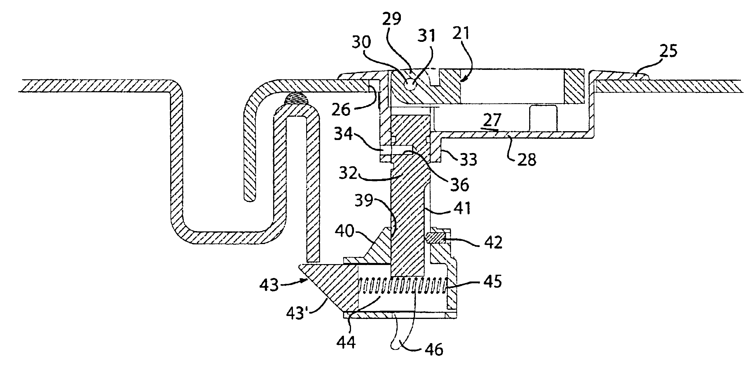
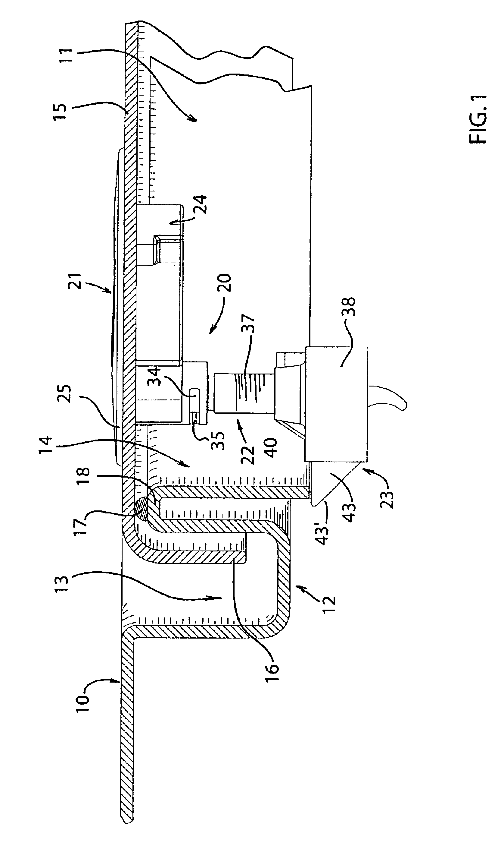
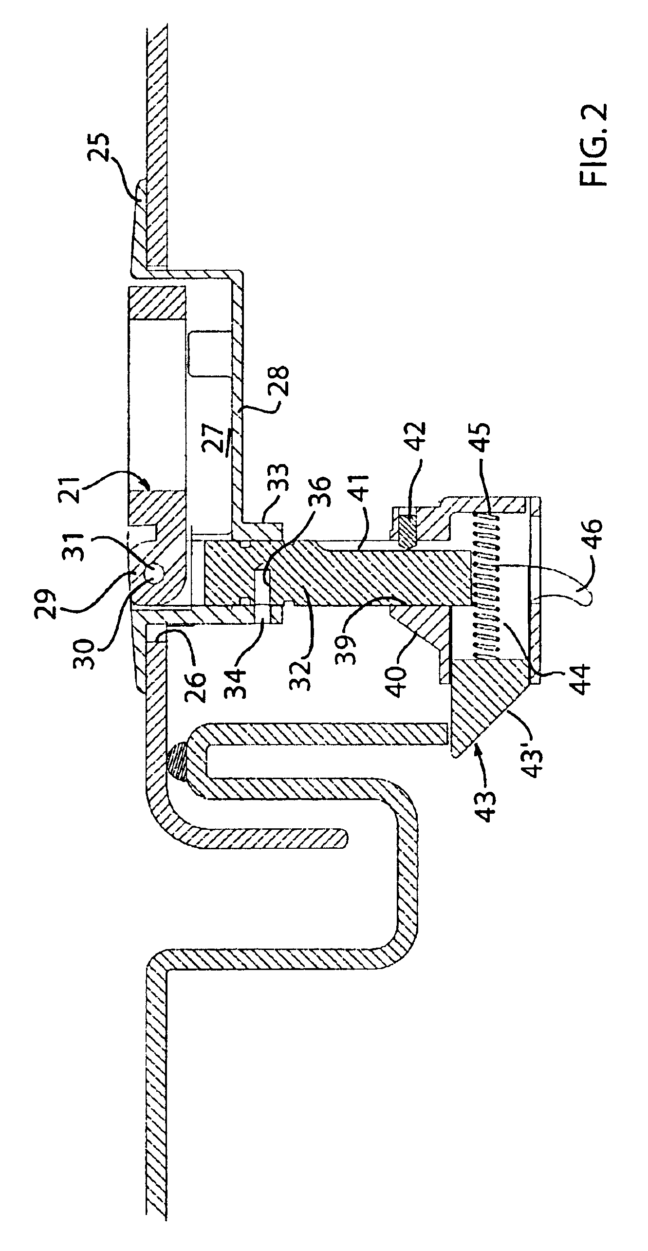
In the Figures, 10 designates a normally horizontal surface, such as the deck of, e.g., a yacht, having therein a typically rectangular hatchway 11, of which only a minor portion is shown. The hatchway is defined by a coaming in the shape of a substantially S-shaped rim 12 integral with the deck and including a substantially U-shaped draining channel 13 and a downwardly turned edge portion 14. A hatch cover 15 having a downwardly turned exterior edge 16 is dimensioned such that the edge 16 is located within the draining channel 13 in the closed position of the hatch shown. A resilient sealing element 17 is attached to the crest portion 18 of the rim 12 joining the draining channel and the edge portion 14 in order to seal the space underneath the hatch cover 15 from the exterior environment.

A locking device 20 according to the present invention is mounted in the hatch cover 15 close to one side thereof. Non-shown hinges are provided along an opposite side of the hatch cover.

The locki...


PUM


Abstract

A locking device includes a handle member, a rotatable member connected to the handle member, and a bolt member connected to the rotatable member so as to follow rotational movements of the handle between a locking position and an unlocking position of the locking device. The bolt member includes a latch bolt spring-loaded towards an extended locking position and operative to yield towards a less extended position when encountering a stationary part of a coaming when positioned in its locking position.

Description

FIELD OF THE INVENTIONThe present invention concerns a locking device of the kind including a handle member, a rotatable member connected to the handle member, and a bolt member connected to the rotatable member so as to follow rotational movements of the handle between an open or unlocked position and a locked position.BACKGROUND OF THE INVENTIONA locking device of this kind is often mounted in a hatch, a door or the like in order to enable locking of the hatch etc., and it is typically operated by turning the handle through 90° between the open and the locked position. Hereby, a free end of the bolt member is moved typically from a position underneath the hatch etc. to a position where it extends outside the limits of the hatch to engage a coaming of the hatch. In an open position of the hatch, it may inadvertently occur that the locking device is in a position where the bolt member projects more or less beyond the limits of the hatch. In case the hatch is slammed in such bolt pos...

Claims


Application Information

Patent Timeline
IPC IPC(8): B63B19/00B63B19/24E05C5/00E05B1/00
CPCB63B19/24E05C5/00E05B1/0092Y10T292/089Y10T292/0871Y10T292/0971Y10T292/0911
Inventor MAGNUSSON, CLAES
Owner SOUTHCO
Why Eureka
Try Eureka