Axial latch actuator

a technology of latch actuator and actuator, which is applied in the direction of coupling device details, coupling device connection, two-part coupling device, etc., can solve the problems of user difficulty in reaching the latch and disengaging a specific modular plug

Inactive Publication Date: 2005-03-08
SIEMON
View PDF11 Cites 69 Cited by
  • Summary
  • Abstract
  • Description
  • Claims
  • Application Information

AI Technical Summary

Problems solved by technology

When there are a number of modular plugs in close proximity (e.g., in a patch panel), each of the modular plugs are located next to each other and it is difficult for the user to reach the latch and disengage a specific modular plug.

Method used


Image

  • Axial latch actuator
  • Axial latch actuator
  • Axial latch actuator

Examples


Embodiment Construction

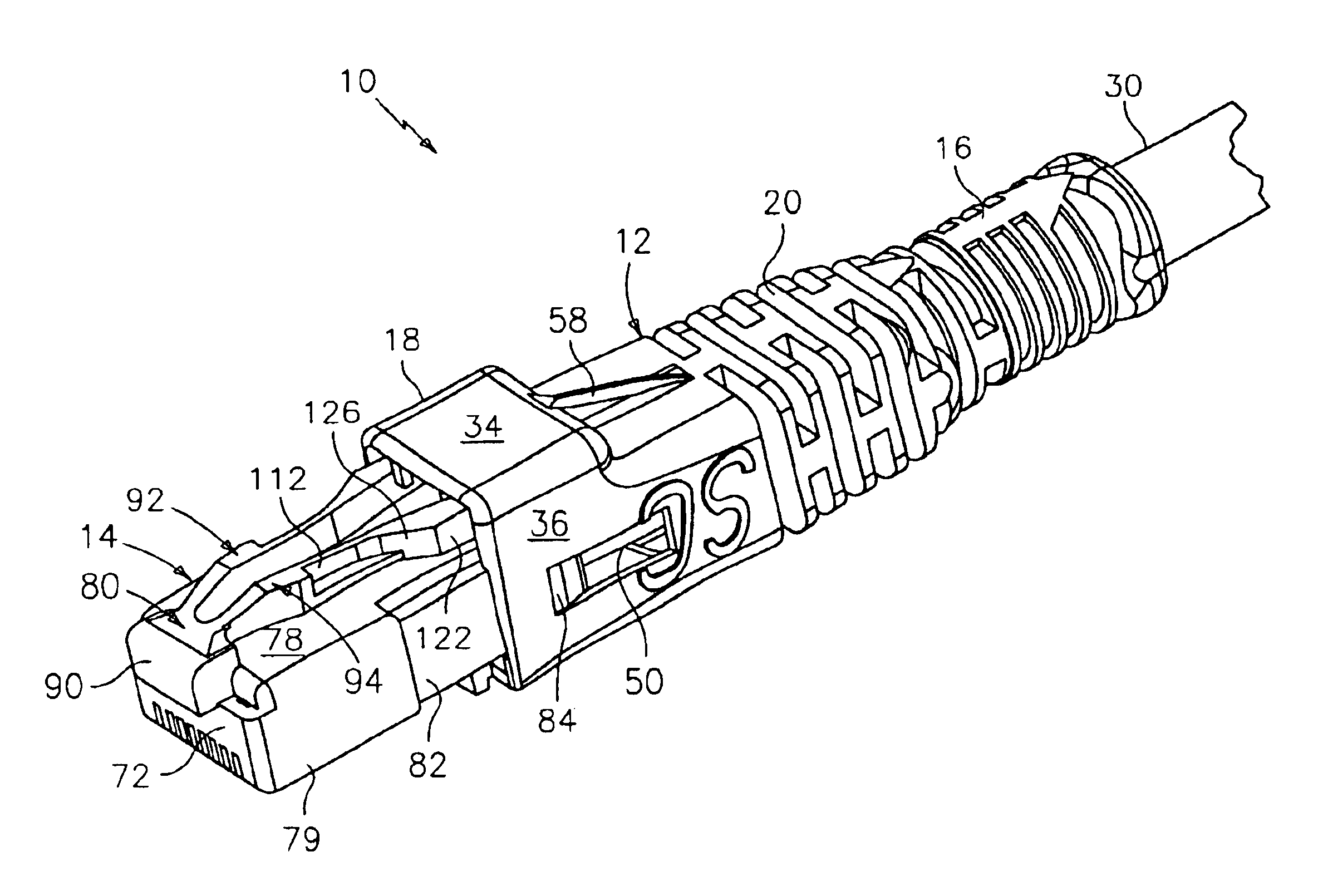
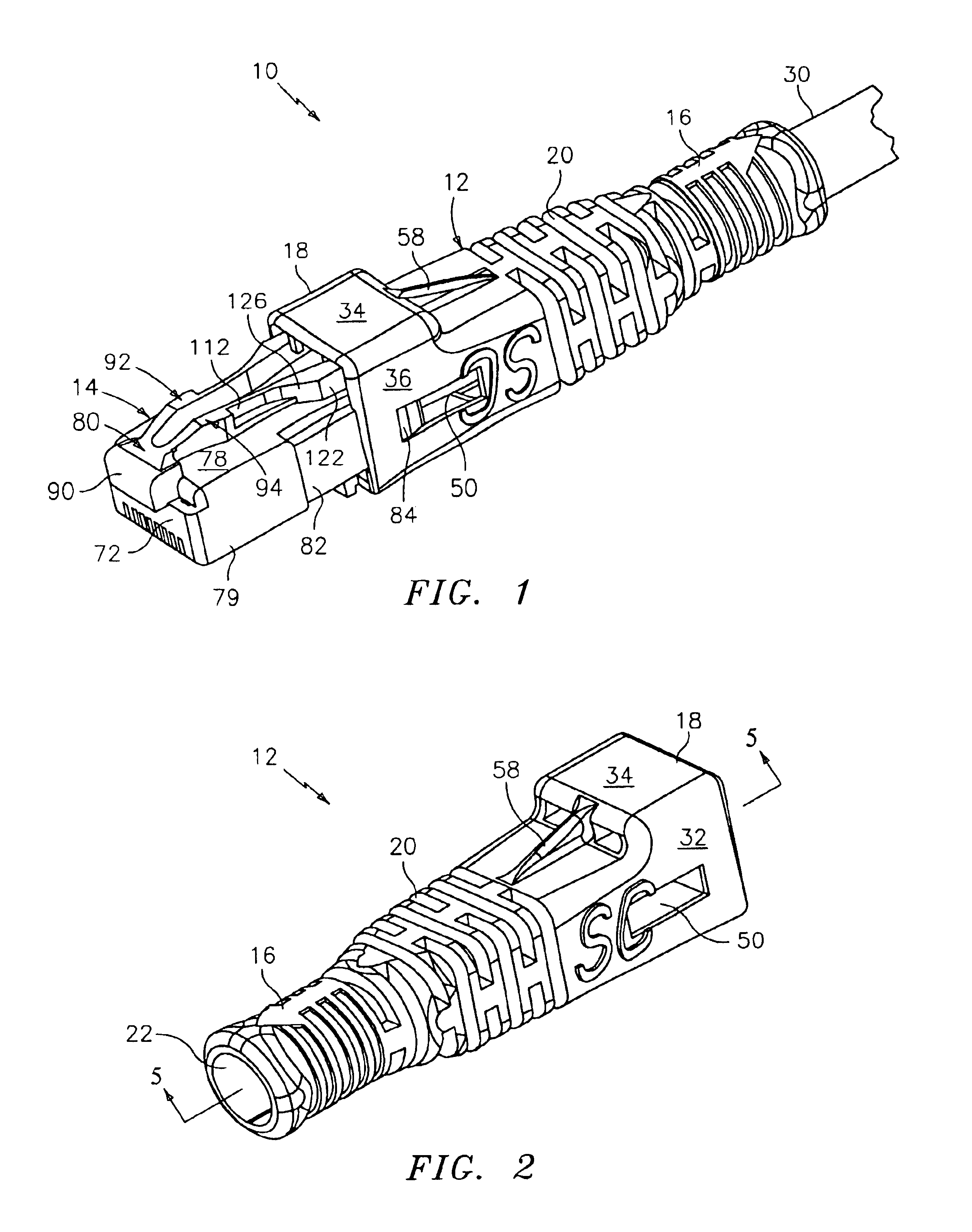
Referring to FIG. 1, a modular plug 10 is illustrated. Plug 10 includes a slidable housing 12 and a mating portion 14. Mating portion 14 is partially received into housing 12.

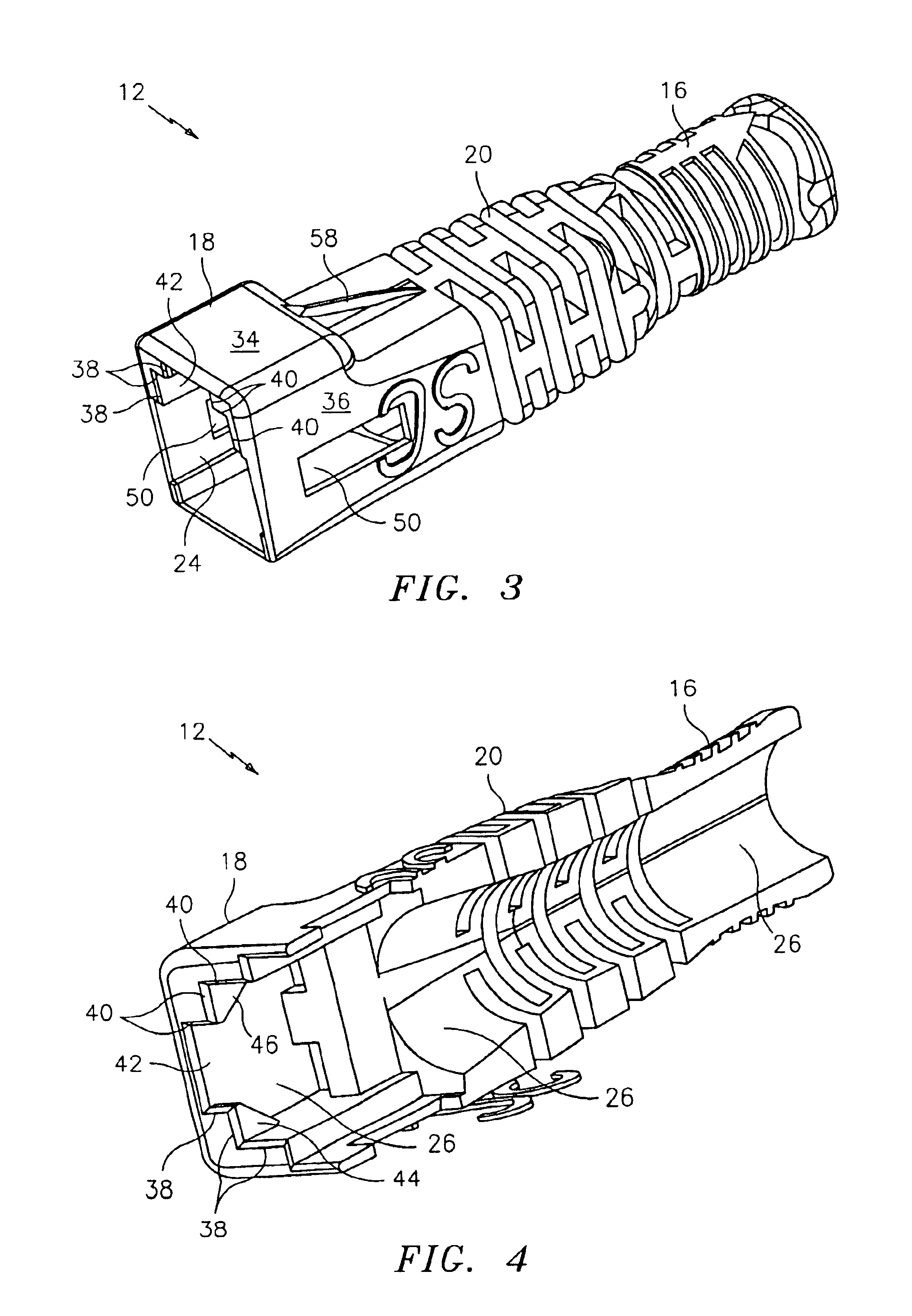
Referring now to FIGS. 1-5, housing 12 has a first end 16, an opposing second end 18, and a middle portion 20. Both first end 16 and second end 18 have openings 22 and 24, with a chamber 26 disposed therebetween. Chamber 26 provides a pathway from first end 16 to second end 18. First end 16 is elongated to allow an operator to grasp housing 12. Opening 22 is sized to receive a cable 30.

Second end 18 is sized to receive mating portion 14. Second end 18 has a first side 32, a second side 34, and a third side 36. First side 32 is approximately parallel to third side 36, with second side 34 located approximately perpendicular to both first side 32 and third side 36.

Housing 12 includes contoured surfaces, which are located within chamber 26 and which engage mating portion 14. The contoured surfaces are as follows. A...


PUM


Abstract

An axial latch actuator includes: a mating portion having a latch surface for engaging a jack; and a slidable housing that slides along the mating portion and engages the mating portion, wherein when the slidable housing slides in a first direction, the mating portion is in a latched position and when the slidable housing slides in a second direction, the mating portion is in an unlatched position.

Description

BACKGROUND OF THE INVENTIONMany prevalent network systems, i.e., Ethernet, etc., require the use of a common modular plug. The modular plug includes opposing first and second ends. The first end is terminated with a cable. The second end is connected to a modular connector, thus forming a modular connection interface. The modular plug connects to a modular jack. The existing manner in which the modular plug is connected to the jack is through the use of a snap latching system, which is illustrated in FIG. 38. The user is required to push down on the latch to disengage the modular plug from the jack. When there are a number of modular plugs in close proximity (e.g., in a patch panel), each of the modular plugs are located next to each other and it is difficult for the user to reach the latch and disengage a specific modular plug.SUMMARY OF THE INVENTIONThe above discussed and other drawbacks and deficiencies of the prior art are overcome or alleviated by an axial latch actuator. In a...

Claims


Application Information

Patent Timeline
Patent Type & Authority Patents(United States)
IPC IPC(8): H01R13/627H01R13/502H01R13/629E05B39/02
CPCH01R13/6272H01R13/629H01R13/502H01R24/64H01R23/10H01R2201/04
Inventor VIKLUND, MARKSTRONKOWSKY, KEVINLO, DENNYYIP, MAXWELL
Owner SIEMON
Why Eureka
Try Eureka