Weighted noise compensating method and camera used in millimeter wave imaging

a weighted noise and imaging technology, applied in the field of millimeter wave imaging, can solve the problems of reducing the effect of diminishing anomalous effects in images, reducing or eliminating the effects of random and inherent noise-responsive and reducing the unpredictable and non-calculable variations in output value signals

Inactive Publication Date: 2005-03-22
MVT EQUITY
View PDF27 Cites 18 Cited by
  • Summary
  • Abstract
  • Description
  • Claims
  • Application Information

AI Technical Summary

Benefits of technology

The present invention involves a new and improved method of reducing or eliminating the effects of the random and inherent noise-responsive variations in output value signals from radiometer channels or receiver channels into which radiant energy from a scene is directed by a movable scanning element during millimeter wave imaging. While efforts have been made in the past to compensate for differences in gain among the channels when composing the millimeter wave image, it is believed that no efforts have been made to reduce the unpredictable and non-calculable variations in output value signals resulting from differences in response characteristics due to random noise. As a consequence of these past practices, the contrast and quality of the millimeter wave images has been diminished.

Problems solved by technology

While efforts have been made in the past to compensate for differences in gain among the channels when composing the millimeter wave image, it is believed that no efforts have been made to reduce the unpredictable and non-calculable variations in output value signals resulting from differences in response characteristics due to random noise.
As a consequence of these past practices, the contrast and quality of the millimeter wave images has been diminished.
Reducing the contribution of the channels which are more noisy and increasing the contribution of the channels which are less noisy has the effect of diminishing anomalous effects in the image which would otherwise occur because of the random and unpredictable effects of noise.

Method used


Image

  • Weighted noise compensating method and camera used in millimeter wave imaging
  • Weighted noise compensating method and camera used in millimeter wave imaging
  • Weighted noise compensating method and camera used in millimeter wave imaging

Examples


Embodiment Construction

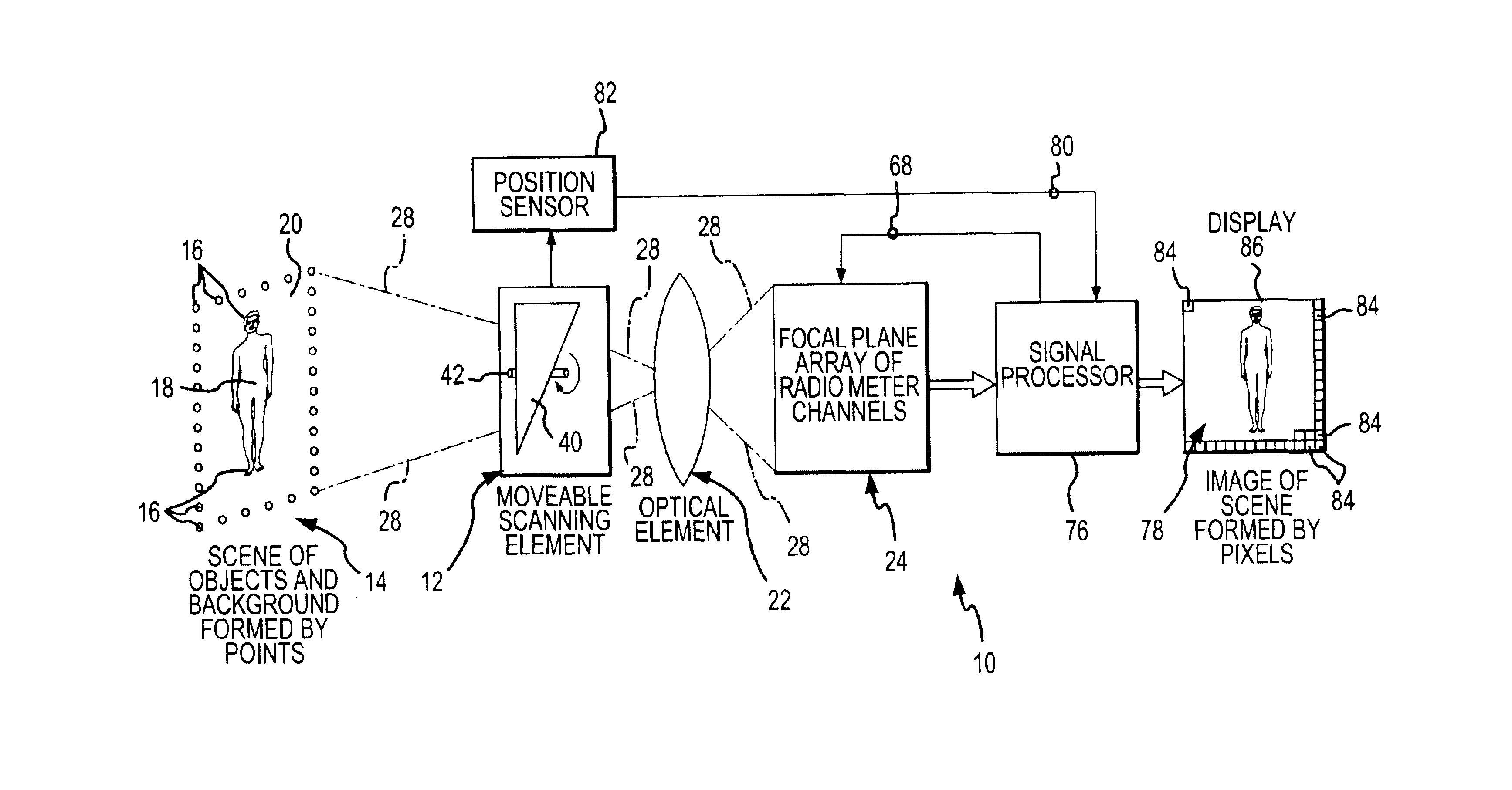
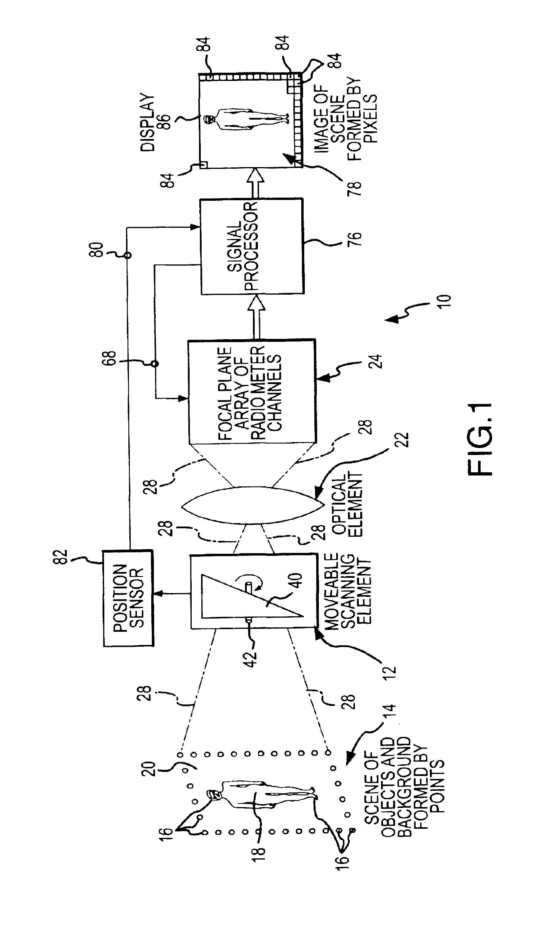
A camera 10, shown in FIG. 1, incorporates and operates in accordance with the various aspects of the present invention. The camera 10 includes a movable scanning element 12 which receives emitted and reflected radiation energy emanated from a scene 14. The scene 14 is formed by points 16, and each of the points 16 is either part of an object 18 within the scene 14 or part of a background 20 within the scene 14. The points 16 of the scene 14 emanate radiation energy with an intensity which is related to the brightness temperature of that point. The emanated radiation energy includes energy in a millimeter wavelength frequency band which is emitted and reflected from the objects 18 and the background 20.

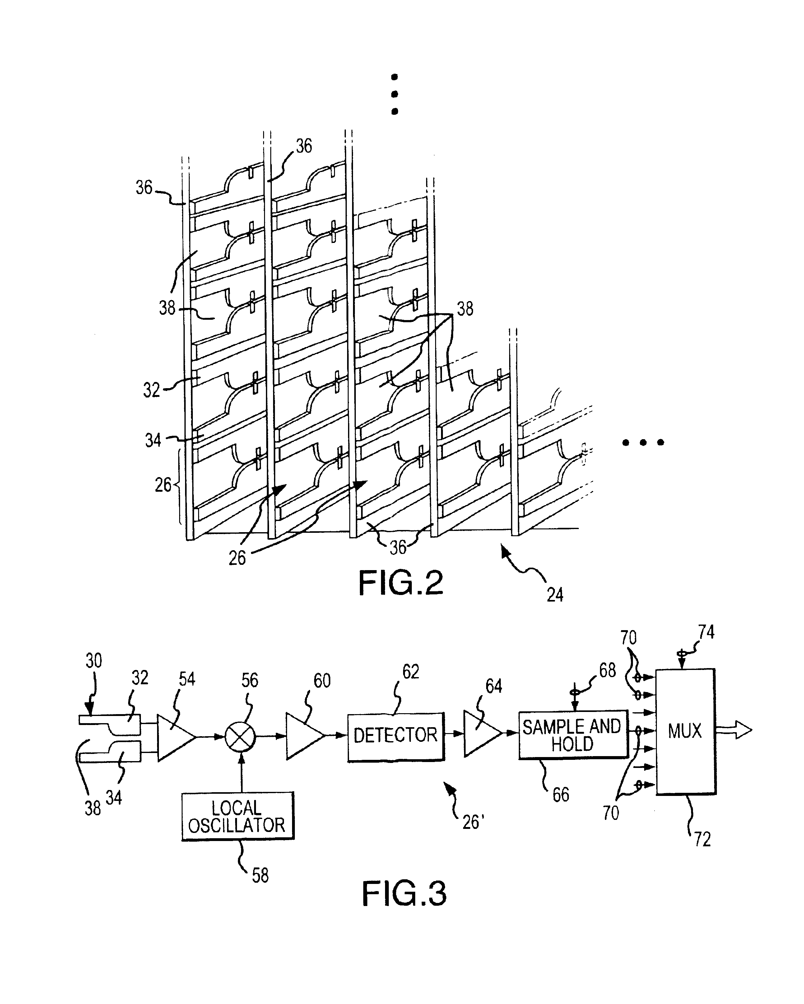
The movable scanning element 12 receives emanated energy from the scene 14, and directs or steers that energy through an optical element 22 to a focal plane array 24 of channels 26. Each channel 26 will typically be a radiometer channel when the camera 10 is used in passive imaging, a...


PUM

PropertyMeasurementUnit
frequenciesaaaaaaaaaa
wavelengthsaaaaaaaaaa
radiant energyaaaaaaaaaa

Abstract

Unpredictable response variations of the output value signals from radiometer or receiver channels due to noise are minimized when composing a millimeter wave image. The image is composed from composition signals which are each related to the corresponding output value signals from the channels. Some composition signals are weighted by a weighting factor which is different from a weighting factor used for weighting other composition signals. Preferably, the reciprocal of the standard deviation of variations of the output value signals from each channel is used as the weighting factor for deriving the composition signals from the output value signals from that channel. The intensity of each pixel of the image is composed by adding the weighted composition signals associated with that pixel.

Description

FIELD OF THE INVENTIONThis invention generally relates to millimeter wave imaging. Millimeter wave imaging involves creating an image of a scene from millimeter wavelength energy signals emanating from the scene. More particularly, the present invention relates to a new and improved method and camera which compensates for the random and unpredictable effects of noise in output value signals supplied by each of a plurality of radiometer channels or receiver channels which receive and detect millimeter wavelength energy signals emanating from a scene. By compensating for the random and unpredictable noise, the individual and particular differences in response of each channel are more accurately compensated to improve the contrast and quality in an image composed by summing the compensated output value signals from the channels.BACKGROUND OF THE INVENTIONMillimeter waves are electromagnetic radiation characterized by wavelengths in the range of from 1 to 10 millimeters and having corre...

Claims


Application Information

Patent Timeline
Patent Type & Authority Patents(United States)
IPC IPC(8): G01N21/01G01J5/00H04N5/217H04N5/30
CPCH04N5/217G01S13/887H04N5/30H04N23/81
Inventor VAIDYA, NITIN M.
Owner MVT EQUITY
Why Eureka
Try Eureka