Isotopically altered optical fiber

a technology of optical fiber and isotope, applied in the direction of glass deposition burners, instruments, manufacturing tools, etc., can solve the problems of loss, net reduction of 11 regeneration stations, etc., and achieve the effect of reducing the gain spectrum of raman

Inactive Publication Date: 2005-03-22
CORNING INC
View PDF11 Cites 11 Cited by
  • Summary
  • Abstract
  • Description
  • Claims
  • Application Information

AI Technical Summary

Benefits of technology

The invention relates to an optical waveguide comprising multiple isotopes of a same chemical element in relative proportions sufficiently changed from a naturally occurring proportion of the isotopes such that the optical losses are reduced in the vicinity of the standard 1510-1610 nm bandwidth, the bandwidth is substantially increased, and the Raman spectrum is broadened. The waveguide preferably is an optical fiber.
As the losses due to Rayleigh scattering remain about the same for wavelengths in the range of about 1500 to 1800, nm while the losses due to infrared absorption in this range are reduced, the net effect is that a new minimum transmission loss of approximately 0.145 dB / km occurs near wavelengths of about 1670 nm. Because the loss curve with respect to wavelength is flatter in the vicinity of the new minimum, bandwidth over a variation of 0.010 dB / km (i.e., in a loss range of between 0.145 and 0.155 dB / km) is increased 17 percent over the 100 nm bandwidth of conventional germanium-doped fiber. If a maximum loss rate of about 0.19 dB / km can be tolerated (which is the minimum loss of the lowest loss germanium-doped fiber presently commercially available), bandwidth can be increased 100 percent. Finally, if a maximum loss rate of 0.200 dB / km can be tolerated (which is the loss rate of conventional fibers) bandwidth can be increased 275 percent.

Problems solved by technology

For example, when conventional fiber is used to form a network traversing the Atlantic Ocean, the optical losses which occur necessitate signal regeneration stations for every 125 km of fiber.
This would result in a net reduction of 11 regeneration stations.

Method used


Image

  • Isotopically altered optical fiber
  • Isotopically altered optical fiber
  • Isotopically altered optical fiber

Examples


Embodiment Construction

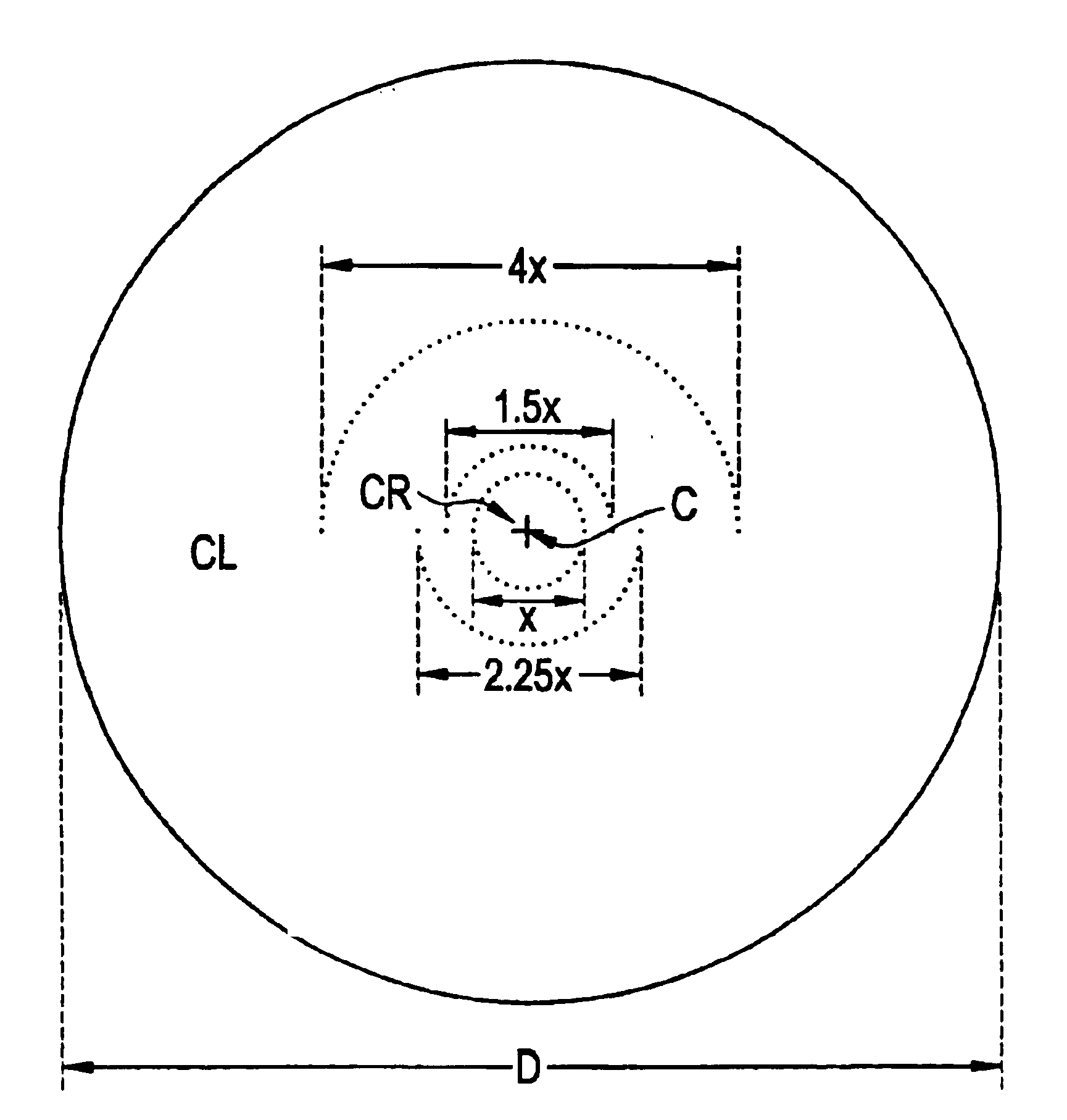
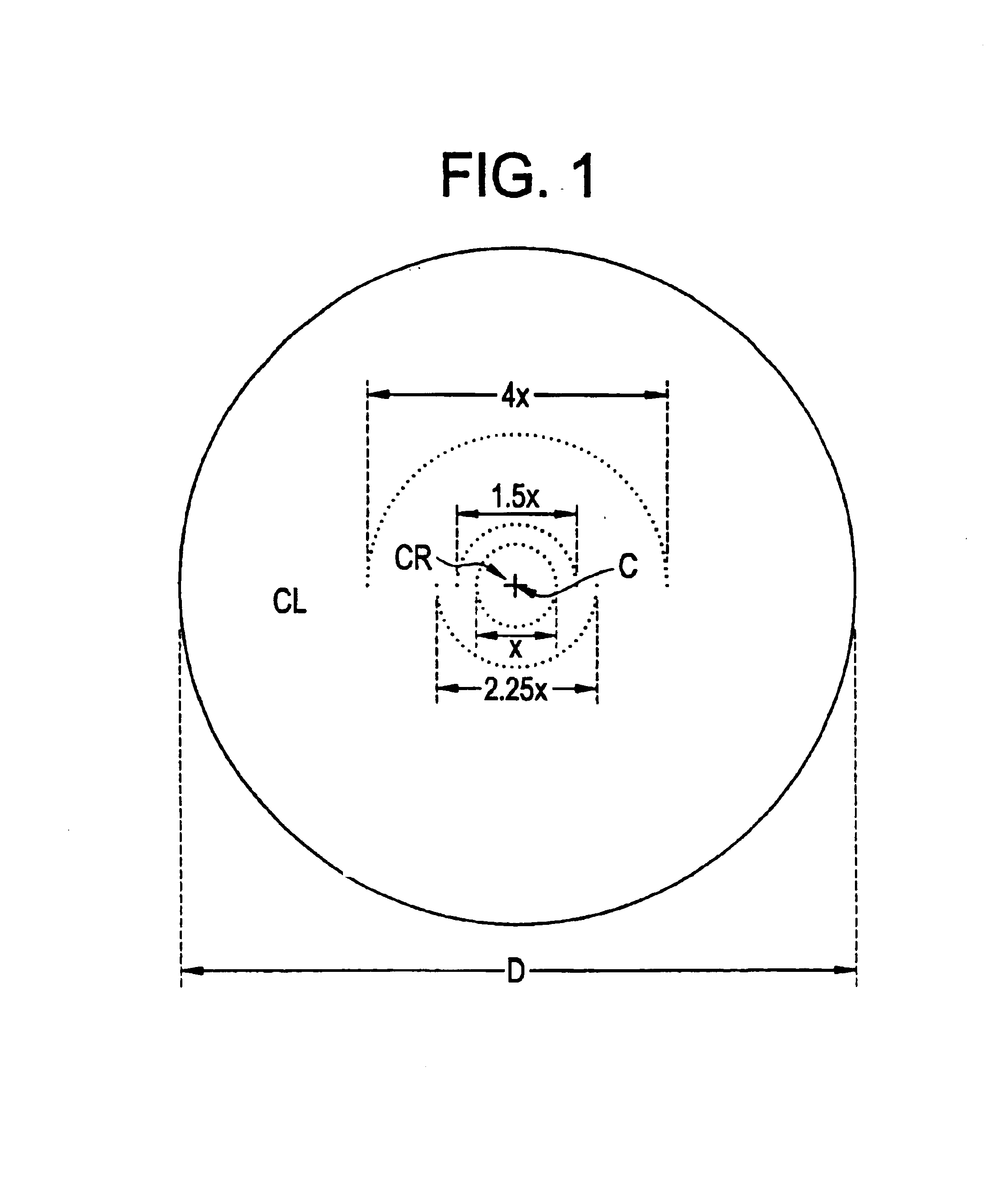
FIG. 1 illustrates one embodiment of the invention comprising a silica optical fiber having core region CR surrounded by a cladding CL, wherein the core region has been enriched with one of the heavier isotopes of either oxygen or silicon. The stable isotopes of silicon have atomic weights of 28, 29, and 30 with natural abundances of 92.23 percent, 4.67 percent, and 3.10 percent, respectively. In the case of oxygen, the stable isotopes have atomic weights 16, 17, and 18, with abundances of 99.762 percent, 0.038 percent, and 0.2 percent, respectively. In both cases, the most abundant isotope constituting silica (SiO2) are the lightest stable isotopes. Stable isotopes are not radioactive and are stable over time and temperatures. The chemical behavior of the aforementioned isotopes are identical to their more abundant, lighter counterparts. Hence, as described in detail hereinafter, the chemical substitution of heavier isotopes such as silicon-30 or oxygen-18 for their lighter counter...


PUM

PropertyMeasurementUnit
wavelengthaaaaaaaaaa
distanceaaaaaaaaaa
distanceaaaaaaaaaa

Abstract

An isotopically-altered, silica based optical fiber is provided having lower losses, broader bandwidth, and broader Raman gain spectrum characteristics than conventional silica-based fiber. A heavier, less naturally abundant isotope of silicon or oxygen is substituted for a lighter, more naturally abundant isotope to shift the infrared absorption to a slightly longer wavelength. In one embodiment, oxygen-18 is substituted for the much more naturally abundant oxygen-16 at least in the core region of the fiber. The resulting isotopically-altered fiber has a minimum loss of 0.044 dB / km less than conventional fiber, and a bandwidth that is 17 percent broader for a loss range between 0.044-0.034 dB / km. The fiber may be easily manufactured with conventional fiber manufacturing equipment by way of a plasma chemical vapor deposition technique. When a 50 percent substitution of oxygen -18 for oxygen-16 is made in the core region of the fiber, the Raman gain spectrum is substantially broadened.

Description

FIELD OF THE INVENTIONThis invention generally relates to an isotopically altered optical fiber, and is specifically concerned with a silica fiber enriched with the heavier isotopes of oxygen and / or silicon in order to reduce transmission losses and to increase bandwidth.BACKGROUND OF THE INVENTIONOptical loss is a limiting factor in the design and construction of optical networks and links, which typically include hundreds of kilometers of silica-based optical fiber. Consequently, a reduction in the loss of the fiber by even hundredths of decibels per kilometer would have a significant impact on the performance of such networks. Optical losses in silica fibers are predominantly caused by two factors, including (1) Rayleigh scattering, which falls off as a function of 1 / λ4 and which dominates for shorter wavelengths, and (2) infrared absorption by the silica, which dominates for longer wavelengths. As is well known in the art, the product of these two forms of optical loss falls to ...

Claims


Application Information

Patent Timeline
Patent Type & Authority Patents(United States)
IPC IPC(8): C03B37/018C03C13/04C03C13/00C03B37/014G02B6/036G02B6/02G02B6/00G02F1/35
CPCC03B37/01413G02B6/03694C03B37/01807C03B37/01823C03B37/01853C03C4/0042C03C13/045C03C13/046G02B6/02G02B6/03644G02B6/03677C03B37/01446C03B2201/20C03B2201/22C03B2201/31C03B2203/22C03B2207/30C03B2207/36G02B6/02228G02B6/02271
Inventor ALLAN, DOUGLAS C.BROWN, JOHN T.CHACON, LISA C.ELLISON, ADAM J. G.FAJARDO, JAMES C.GRAY, STUARTHOUSE, KEITH L.KOCH, III, KARL W.POWERS, DALE R.WEST, JAMES A.
Owner CORNING INC
Why Eureka
Try Eureka