High speed bagging system and method

a bagging system and high-speed technology, applied in the field of high-speed bagging system and method, can solve the problems of increasing the speed of the machine, increasing the speed of the conveyor, etc., and achieve the effect of high output speed and high output speed

Inactive Publication Date: 2005-04-05
GLOPAK INC
View PDF14 Cites 26 Cited by
  • Summary
  • Abstract
  • Description
  • Claims
  • Application Information

AI Technical Summary

Benefits of technology

Another feature of the present invention is to provide a high output speed bagging system and method which can operate at higher speed outputs than those of the prior art and capable of producing filled bags at a rate of at least 140 bags per minute.
Another feature of the present invention is to provide a high output speed bagging system and method which can operate substantially on a continuous basis regardless if film rolls have to be installed in the filling machines or if film bags have to be installed on the baggers or if one filler is stopped, etc. Accordingly, the production is continuous.
Another feature of the present invention is to provide a high output speed bagging system and method and wherein a single service person can operate two of these high speed bagging systems disposed such as to optimize floor space area and accessibility to a service person.

Problems solved by technology

However, there is a need to increase this speed in existing facilities having restricted space area.
There are several problems in increasing the speeds of these machines as an increase in the bagging necessitates an increase in the speed of the conveyors.
The bag slippage is due to the high speed of the conveyors and the fact that these bags are formed of polyethylene which is slippery, and have a flexible product inside, such as water or milk.
Accordingly, increasing the speed of the conveyor has not proved to be a viable solution.
Another disadvantage of the equipment of known systems is that they are not ergonomically positioned for servicing by a single person.

Method used


Image

  • High speed bagging system and method
  • High speed bagging system and method
  • High speed bagging system and method

Examples


Embodiment Construction

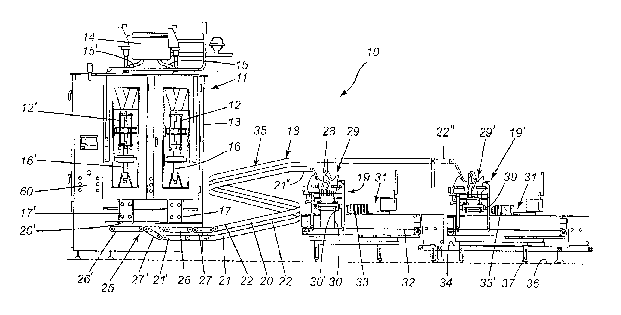
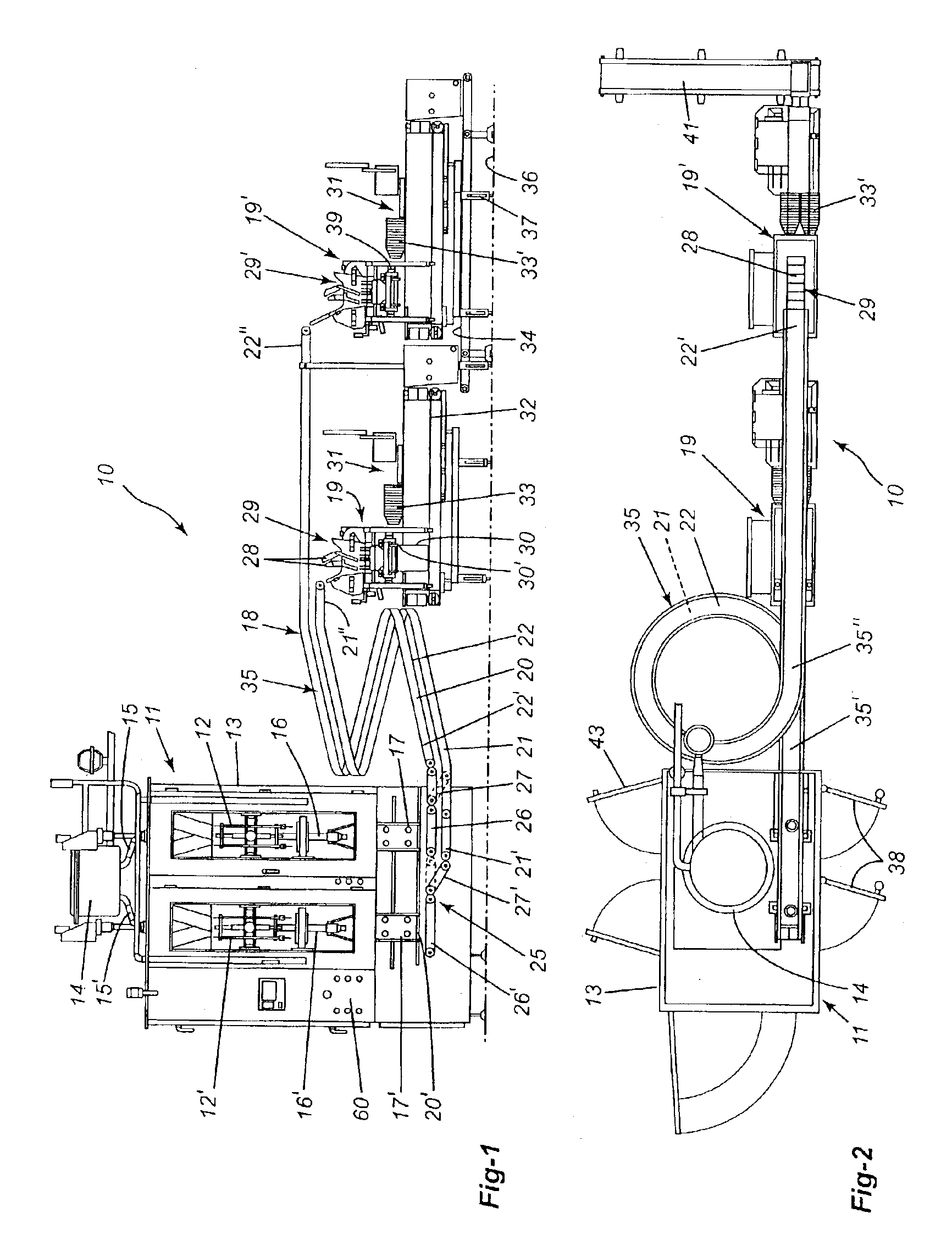
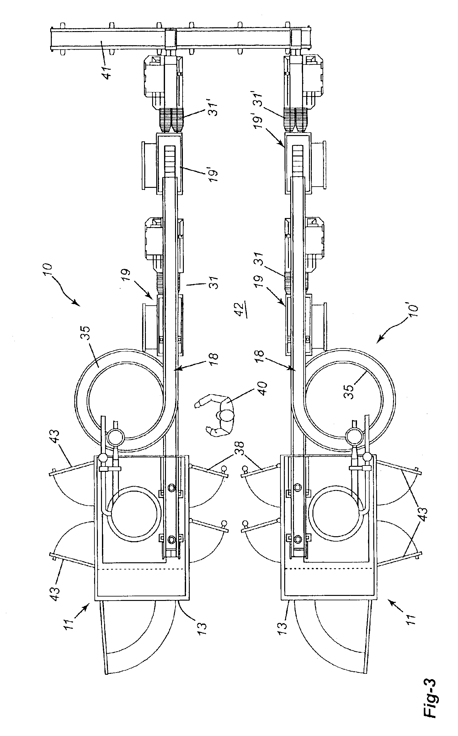
Referring now to the drawings, and more particularly to FIG. 1, there is shown generally at 10 the high speed bagging system of the present invention. The system comprises a vertical form, fill and seal bagging machine 11 (VFFS) which comprises two bag forming, filling and sealing heads 12 and 12′ housed in a common housing 13 for placing a liquid product, such as milk or water, into bags formed therein. The milk or water is fed from a holding tank 14 located at the top of the housing 13 and feeds the milk or water through feed conduits 15 and 15′ feeding respective filler tubes 16 and 16′. The filled bags are then released in chutes 17 and 17′, respectively, disposed over a conveyor system 18. These bag forming, filling and sealing machines are well known in the art and will not be described in more detail herein.

As previously described, such systems usually feed a single bagging machine such as one of the bagging machines 19 and 19′ as hereinshown. However, in order to increase th...


PUM

PropertyMeasurementUnit
angleaaaaaaaaaa
anglesaaaaaaaaaa
anglesaaaaaaaaaa

Abstract

A high speed bagging system and a method for placing a liquid product into a bag and placing at least two of these bags into a pouch is described. The system comprises at least two bag fillers housed in a common filler housing and operating simultaneously to place the liquid product in respective bags on a continuous basis during a working cycle. Filled bags are simultaneously conveyed on a two lane conveyor system. The two-lane conveyor is configured to optimize floor space area. Each conveyor belt has an outlet end associated with a respective bagging machine at a bagging station. The bagging machines are adapted to place at least two of the bags into a pouch on a continuous basis during the working cycle. The bagging machines feed a respective pouch closure device to close a mouth opening of the pouches which are then discharged on a discharge conveyor.

Description

TECHNICAL FIELDThe present invention relates to a high speed bagging system and method, and particularly, but not exclusively, for bagging milk and wherein the system can operate at higher output speeds than known prior art systems and further wherein the bagging system of the present invention optimizes floor space area and is ergonomic to a service person who can maintain two of these systems operative.BACKGROUND ARTIn the milk bagging industry, the current practice is to use twin-head bag forming, filling and sealing machines to bag milk at high speeds. The current speed of operation of such machine is about 120 bags per minute. However, there is a need to increase this speed in existing facilities having restricted space area. There are several problems in increasing the speeds of these machines as an increase in the bagging necessitates an increase in the speed of the conveyors. When the conveyor speeds are increased, the bags slip and pile up on one another. The bag slippage i...

Claims


Application Information

Patent Timeline
Patent Type & Authority Patents(United States)
IPC IPC(8): B65B9/10B65B9/20B65B65/00B65B9/207
CPCB65B9/20B65B61/28B65B65/003B65B2220/20B65B2210/02
Inventor BASQUE, ROLAND
Owner GLOPAK INC
Why Eureka
Try Eureka