Capacitive angular position sensor

Inactive Publication Date: 2005-04-05
DELPHI TECH INC
View PDF3 Cites 23 Cited by
  • Summary
  • Abstract
  • Description
  • Claims
  • Application Information

AI Technical Summary

Benefits of technology

This present invention is directed to the provision of an improved angular position sensor. More particularly, this present invention

Problems solved by technology

Whereas some known capacitive position sensors are generally effective to provide an accurate indication of angular position in a non-contact environment, t

Method used


Image

  • Capacitive angular position sensor
  • Capacitive angular position sensor
  • Capacitive angular position sensor

Examples


Embodiment Construction

The sensor assembly of the present invention is intended for use in measuring the angular position of any rotatable body, but is especially suitable for use in automotive applications where it is desired to determine the angular position of a rotating shaft, such as, for example, the vehicle steering column shaft.

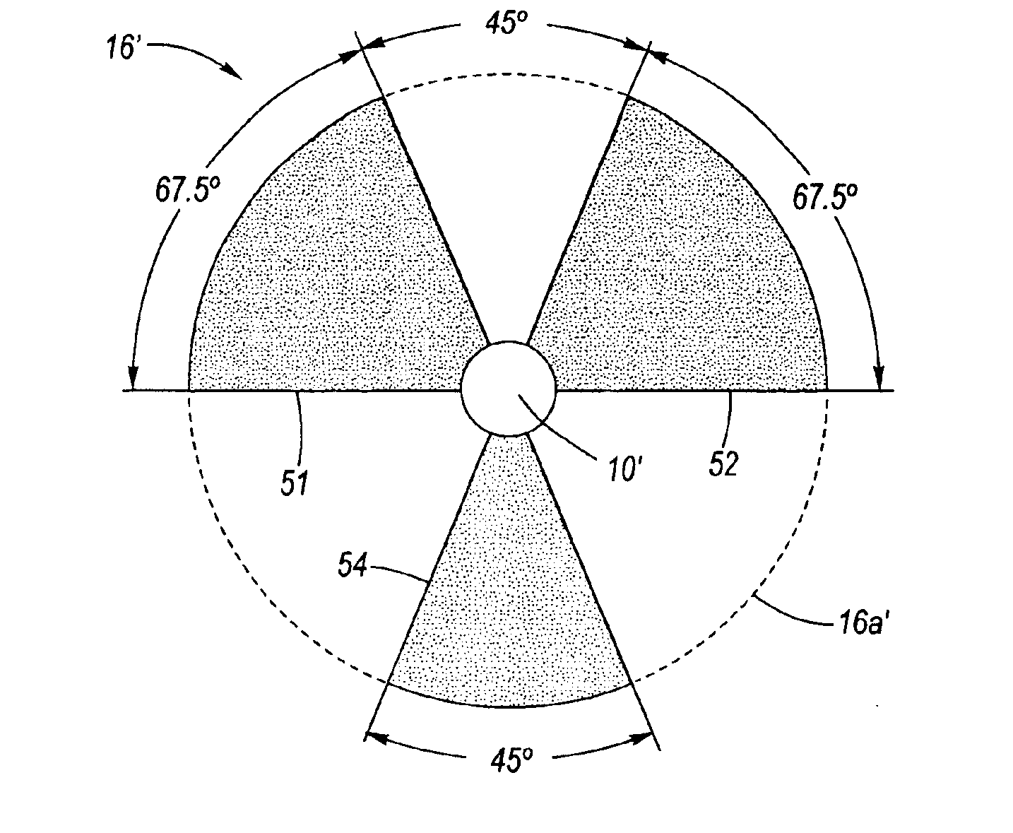
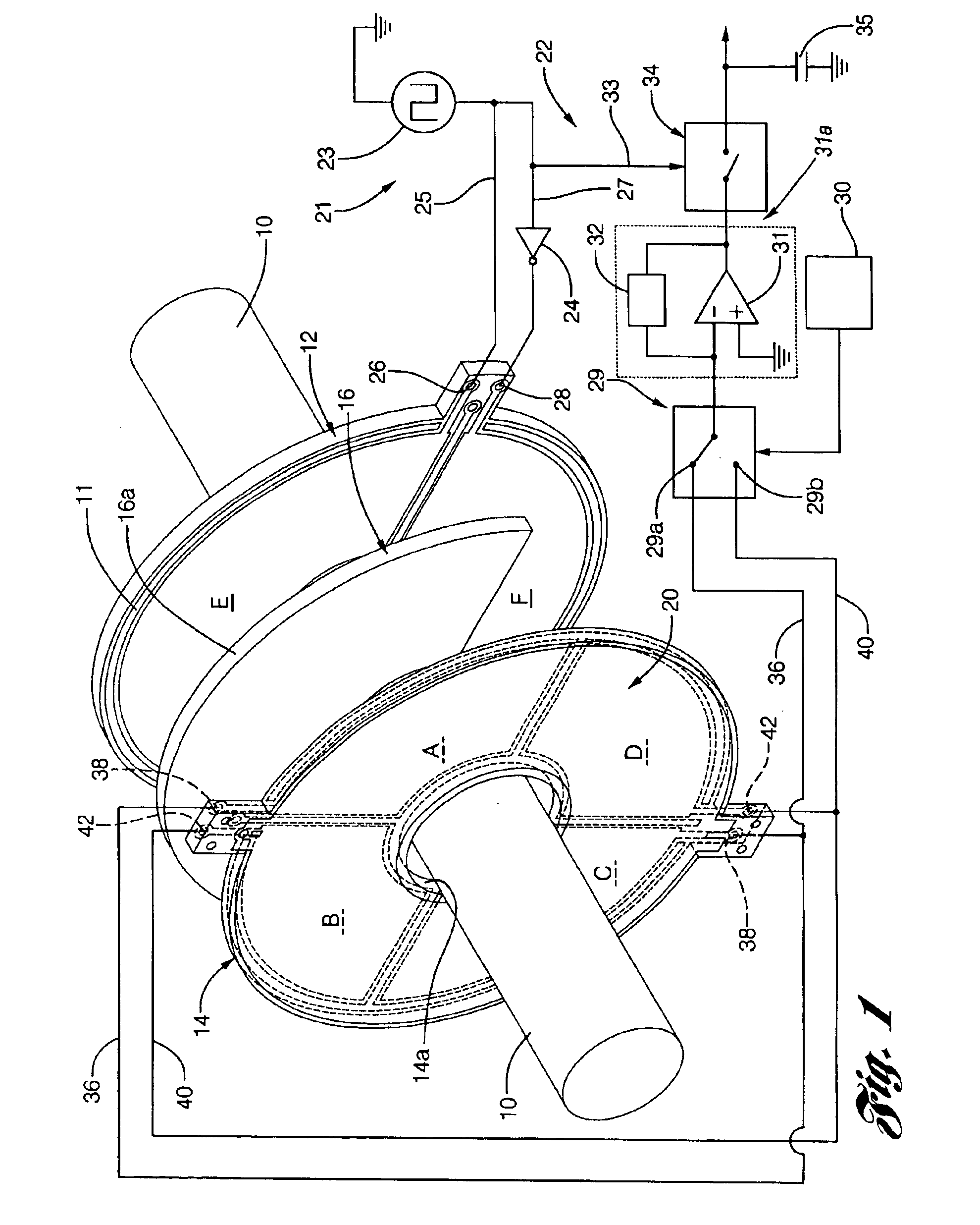
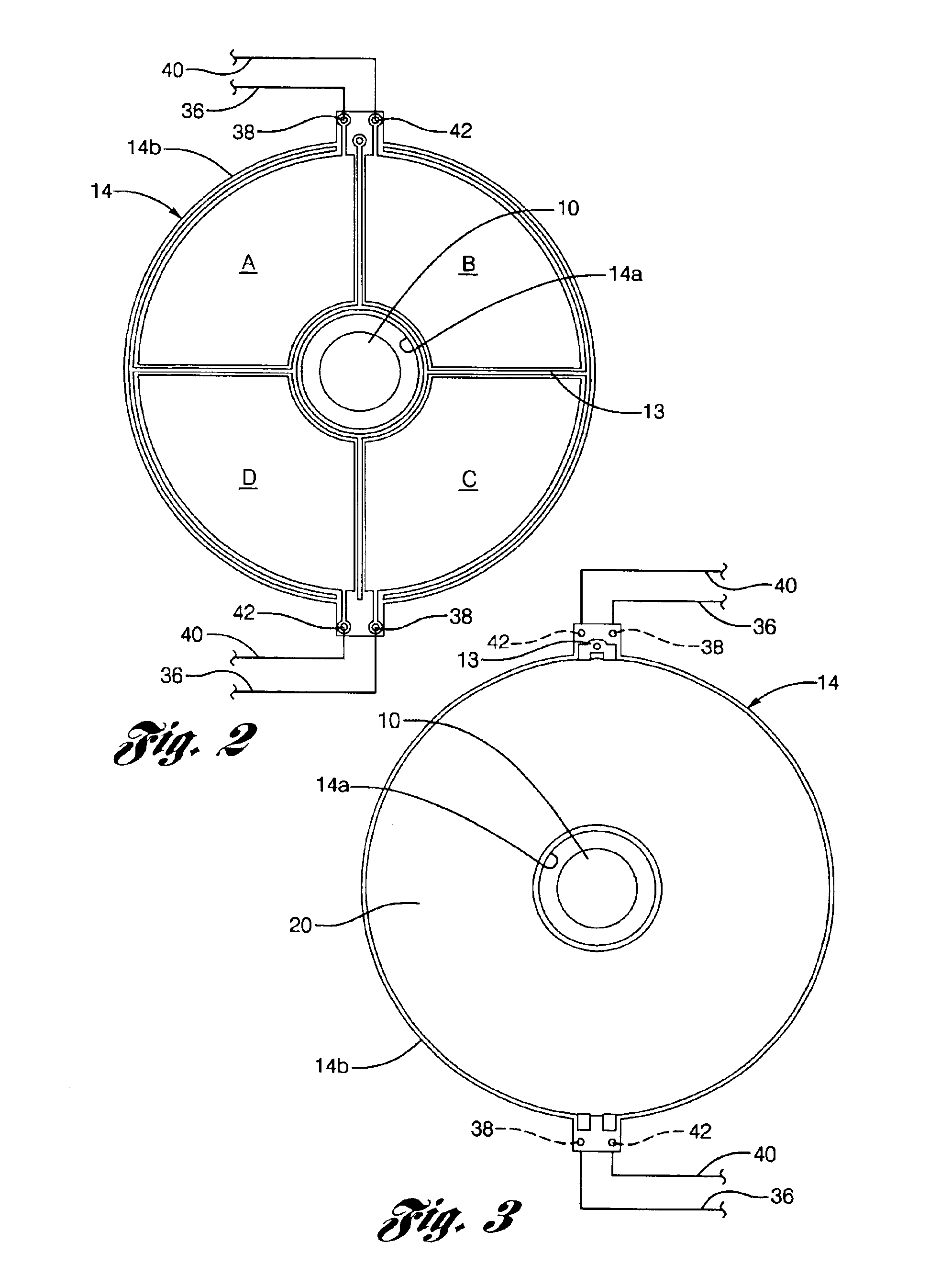
The sensor of the first aspect of the present invention is illustrated for use with a shaft, such as the shaft 10 seen in FIG. 1 (in the example above, the steering column shaft) and, broadly considered, includes a transmitter plate 12, a receiver plate 14, a rotor 16 and sensor electronics 21, 22.

As shown in detail in FIGS. 4 and 5, the transmitter plate 12, utilized in the first and second aspects of the present invention, has a generally circular configuration and includes a central hole 12a sized to freely pass shaft 10. One face of the plate 12 is electrically shielded by a shield 18 and the other face of the plate 12 is divided into two equally-sized, semicircular tra...


PUM


Abstract

A sensor assembly for sensing angular position of one object relative to another object. A capacitor is formed between a transmitter capacitor plate having a pair of transmitter electrodes and a receiver capacitor plate having preferably eight receiver electrodes forming four receiver electrode pairs. A dielectric rotor rotates between the plates, the rotor having first and second segments each subtending 67.5 which are mutually separated by a vacancy subtending 45 degrees, and further having a third segment subtending 45 degrees disposed between the first and second segments diametrically opposite the vacancy. An electrical circuit measures net charge induced on each of the receiver electrode pairs, wherein the charges indicate the angular position of said rotor relative to said transmitter and receiver capacitor plates.

Description

TECHNICAL FIELDThis present invention relates to position sensors and particularly to angular or rotary position sensors.BACKGROUND OF THE INVENTIONPosition measurements, including both linear and angular measurements, are widely implemented in industrial automation control. In particular, the automotive industry is using more and more linear / angular position sensors for closing various control loops. For example, sensors are used in steer-by-wire systems to determine the angular position of the steering column; sensors are used to determine the angular position of the throttle in engine control modules; sensors are used to determine the brake pedal position and / or the brake master cylinder position in brake-by-wire systems; and sensors are used in vehicle smart suspension systems.Known technologies that can be used to determine angular position include contact measurement, such as a resistance stripe, or non-contact measurement effects, based on inductance, capacitance, optical, or...

Claims


Application Information

Patent Timeline
IPC IPC(8): G01D5/24G01D5/12
CPCG01D5/2405
Inventor LIN, YINGJIENICHOLSON, WARREN BAXTER
Owner DELPHI TECH INC
Why Eureka
Try Eureka