Power line device with directional coupler

Active Publication Date: 2015-03-24
SOLAIRENC LLC
View PDF3 Cites 8 Cited by
  • Summary
  • Abstract
  • Description
  • Claims
  • Application Information

AI Technical Summary

Benefits of technology

[0006]It is a further object, feature, or advantage of the present invention to provide an improved PLC modem.
[0007]It is a still further object, feature, or advantage of the present invention to provide a PLC modem that allows for properly matching the high-frequency characteristics of the power line and avoids problems associated with impedance mismatch.
[0008]Yet a further object, feature, or advantage of the present invention is to provide a PLC modem that allows for sensing detection of mismatch.
[0009]One or more of these and or other objects, features, or advantages of the present invention will become apparent from the specification and claims that follow. No single embodiment of the present invention need provide all of these objects, features, or advantages and the present invention is not to be limited to or by these objects, features, or advantages.
[0010]According to one aspect of the present invention, a power line carrier modem is configured for coupling to AC power lines. The power line carrier modem includes a processor, an output from the processor, a plurality of inputs to the processor, and a directional coupler operatively connected to the output, the plurality of inputs, and the AC power lines. The power line carrier modem may further include a digital-to-analog-converter operatively connected to the output from the processor. The output from the processor may be an output bus. The power l

Problems solved by technology

It is a common problem, however, that most PLC modem transmitters do not properly match the high-frequency characteristics of the power line and hence, transmit with less than optimal efficiency and transmit in frequency ranges where little power is actually passed onto the power lines.
Impedance mismatches can a

Method used


Image

  • Power line device with directional coupler
  • Power line device with directional coupler
  • Power line device with directional coupler

Examples


Embodiment Construction

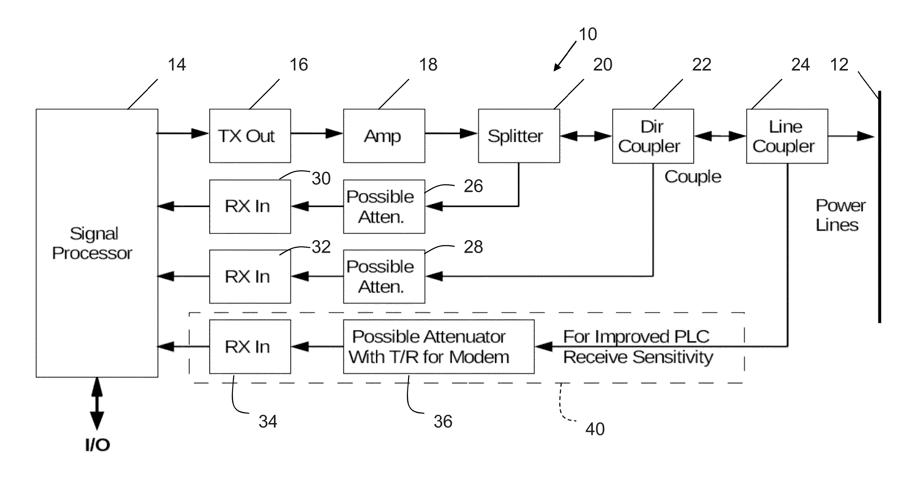
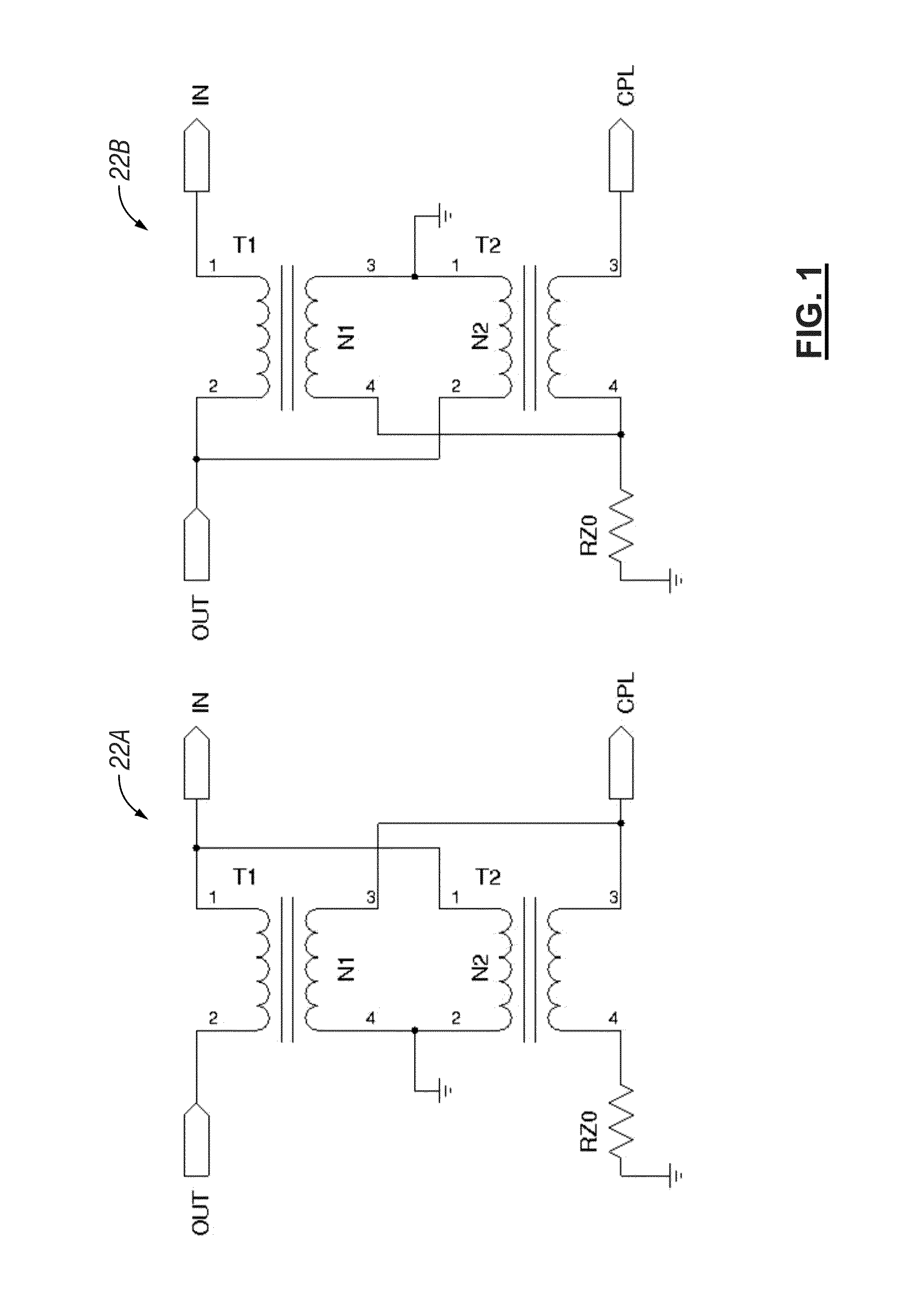
[0033]The present invention provides for adding a directional coupler to the output of the PLC transmitter either prior to or as part of the power line coupler. A directional coupler may be realized in many ways as is commonly known in the art. Two examples of directional couplers 22A, 22B are shown in FIG. 1.

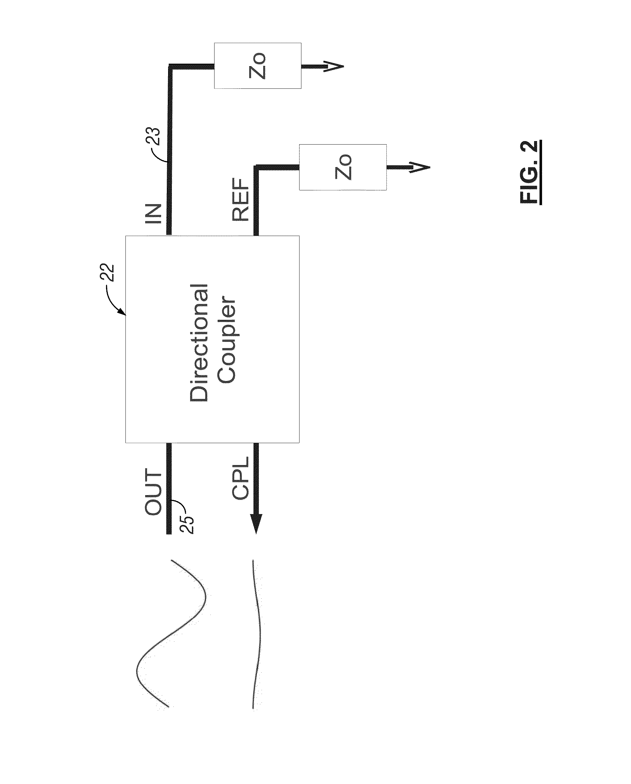
[0034]Directional couplers typically have three or four terminals and are commonly used to selectively couple signals onto the Coupled terminal based upon mismatches being present between various terminals. One use of a directional coupler is to serve as a “reflectometer” and provide a means of measuring signal being reflected from a load. The directional coupler is usually designed to have a characteristic impedance (commonly 50 or 75 Ohms) which is application dependant. In a typical application, shown in FIGS. 2-4, the Coupled output is seen to vary in amplitude and phase depending upon the impedance applied to the directional coupler IN pin 23. If a signal is applied to the...


PUM


Abstract

A power line carrier modem is configured for coupling to AC power lines. The power line carrier modem includes a processor, an output from the processor, a plurality of inputs to the processor, and a directional coupler operatively connected to the output, the plurality of inputs, and the AC power lines. The power line carrier modem may further include a digital-to-analog-converter operatively connected to the output from the processor. The output from the processor may be an output bus. The power line carrier modem further includes an analog-to-digital-converter operatively connected to the plurality of inputs to the processor. The power line carrier modem may be configured to perform Vector Network Analysis functions. The power line carrier modem may be configured to indicate PLC modem transmit frequencies being reflected from the AC power lines or the line coupler. The transmitter functions may be implemented in software by the processor to provide a transmit output on the output line. Receiver functions may also be implemented in software by the processor.

Description

CROSS-REFERENCE TO RELATED APPLICATIONS[0001]This application claims priority under 35 U.S.C. §119 to provisional application Ser. No. 61 / 318,151 filed Mar. 26, 2010, herein incorporated by reference in its entirety.GRANT REFERENCE[0002]This invention was made with government support under Contracts W31P4Q-05-C-R067 and W31P4Q-06-C-0221 awarded by the U.S. Army Aviation and Missile Command. The government has certain rights in the invention.FIELD OF THE INVENTION[0003]The present invention relates to power line carrier (PLC) modems. More particularly, the present invention relates to improved power line carrier modems which incorporate a directional coupler.BACKGROUND OF THE INVENTION[0004]In power line communications, power lines are used as a transmission medium. Power Line Carrier modems transmit high frequency signals over a power line and the signals may be narrow-band (perhaps a few kHz wide) or up to broad-band (many MHz wide). These devices are usually capacitively or induct...

Claims


Application Information

Patent Timeline
IPC IPC(8): H04B1/38
CPCH04B3/56H04B2203/5425H04B2203/5483
Inventor BLACK, WILLIAM C.
Owner SOLAIRENC LLC
Why Eureka
Try Eureka