Rotary disk type storage device

a storage device and disk drive technology, applied in the field of rotary disk drive storage devices, can solve the problems of damping the vibration of the side wall of the cover casing, vibrations causing noise, and vibrations affecting the contruction of the record carrier

Inactive Publication Date: 2005-04-05
WESTERN DIGITAL TECH INC +1
View PDF12 Cites 3 Cited by
  • Summary
  • Abstract
  • Description
  • Claims
  • Application Information

AI Technical Summary

Benefits of technology

The invention aims to solve the problem of vibration-induced noise in a simple way. The technical effect of the invention is to reduce the noise caused by vibration in a rotary disk type storage device.

Problems solved by technology

The technical problem addressed in this patent is to reduce the size, weight, noise, and cost of a rotary disk type storage device, particularly in smaller magnetic disk drives where the thickness of the cover casing cannot be reduced without compromising its rigidity. The patent proposes a solution to suppress vibrations of the cover casing during the seek operation of the actuator, which is the main source of noise, without adding much weight or cost.

Method used


Image

  • Rotary disk type storage device
  • Rotary disk type storage device
  • Rotary disk type storage device

Examples


Embodiment Construction

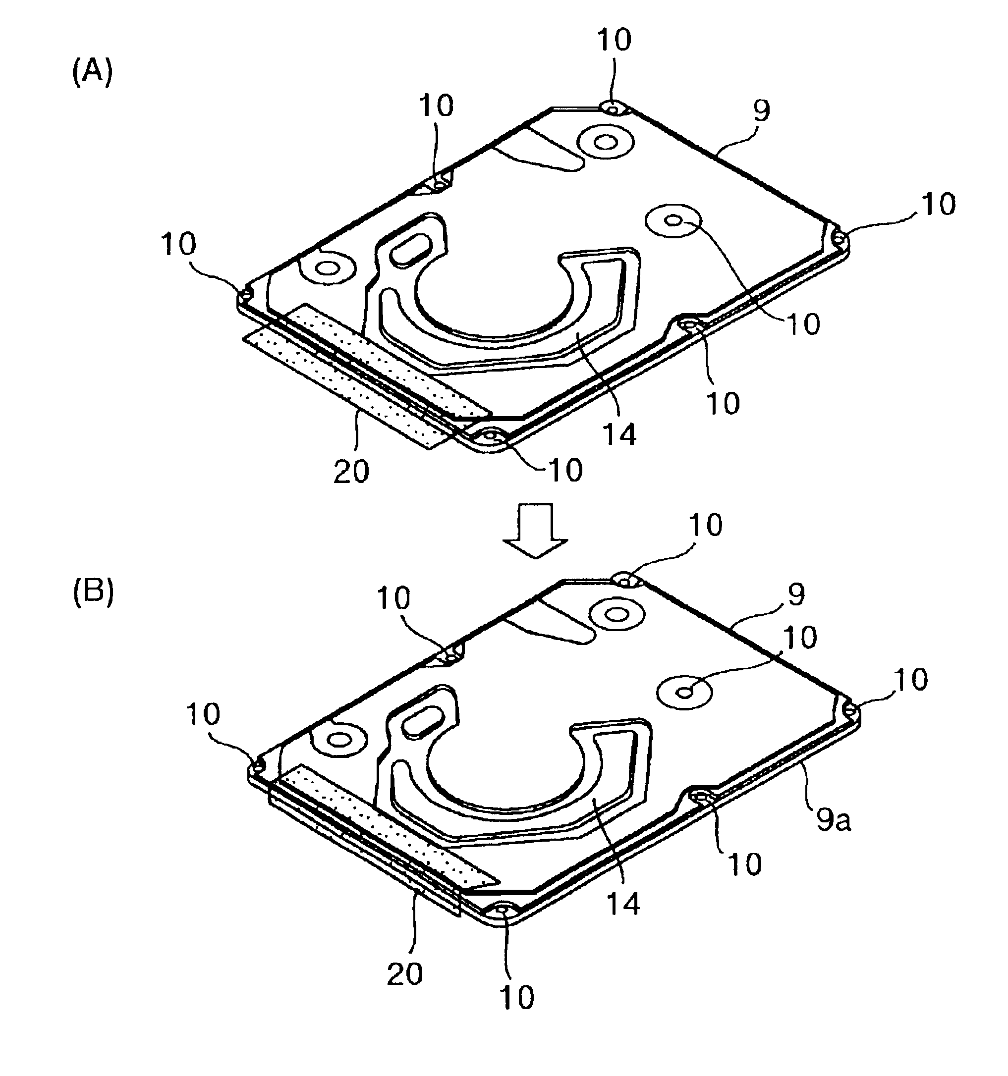
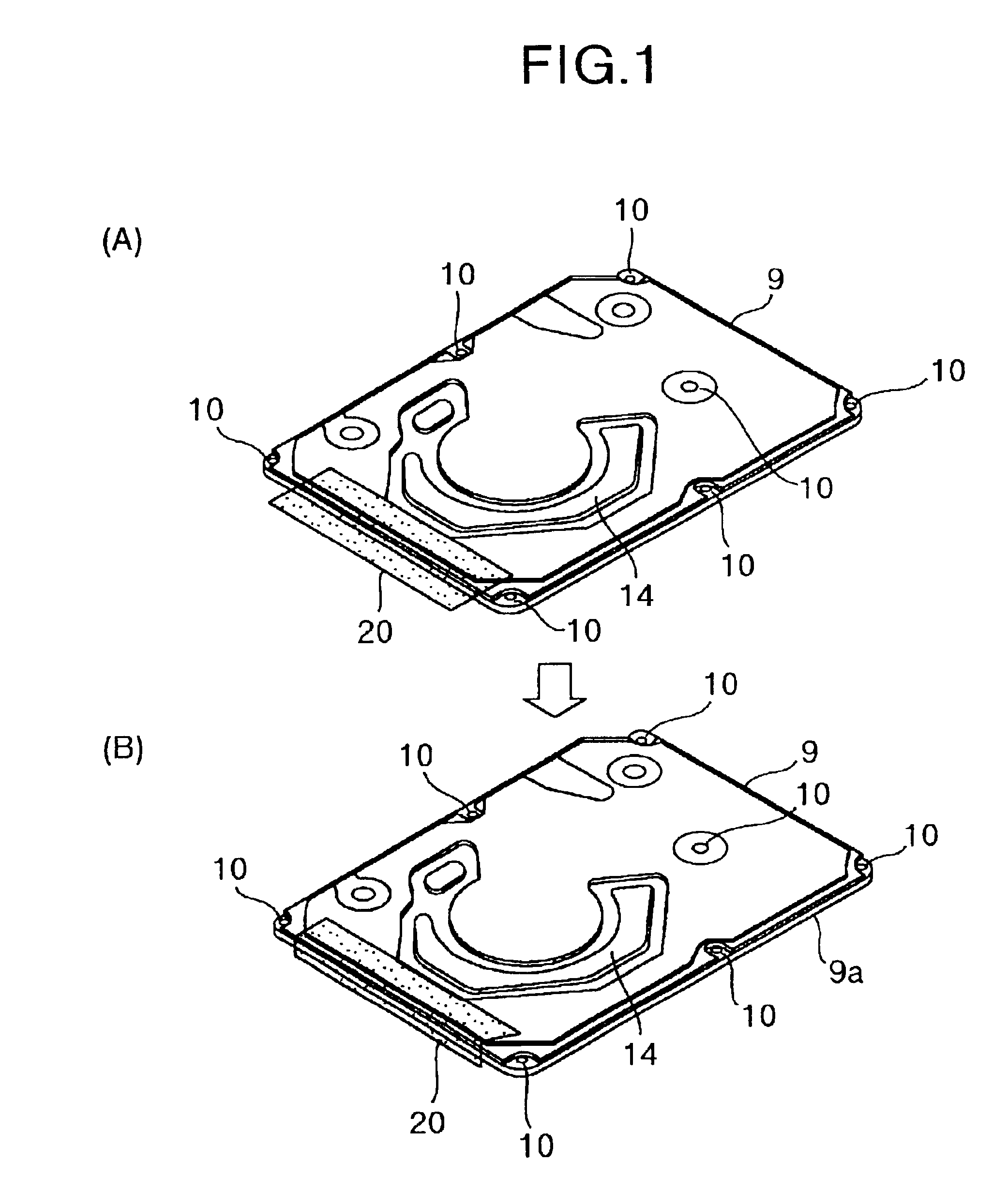
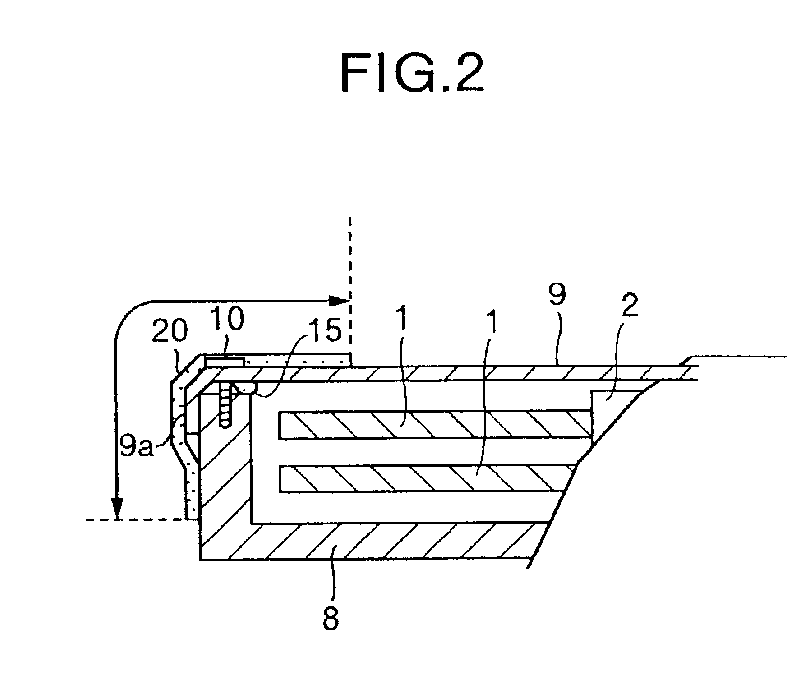
Description will be now made, with reference to FIGS. 1 to 5, on an embodiment in which the invention is applied to a magnetic disk drive. FIGS. 1A and 1B are outside views of the embodiment in which a film member is bonded to the magnetic disk drive according to the invention. FIG. 2 is an explanatory view in which a part of FIG. 1 is cut away and enlarged. FIG. 3 is a view showing the overall construction of the magnetic disk drive, at which the invention is targeted, in a state of removing a cover casing. FIG. 4 is a view for explanation of the arrangement of parts in a base casing and the locations of screws for fastening together the cover casing and the base casing. FIG. 5 is a view for explanation of vibration modes of the cover casing.

The size of the casings of magnetic disk drives is standardized. In the case of a 2.5-inch type, for example, the drive has a construction as shown in FIG. 3. More specifically, one or more magnetic disks 1, serving as recording mediums, are se...


PUM


Abstract

A rotary disk type storage device has a casing comprised of a box-shaped base casing, whose one side is opened, and a cover casing closing the open side of the base casing, in which accommodated are a magnetic disk, a spindle for rotating the magnetic disk, and an actuator for moving a magnetic head slider to a desired position on the magnetic disk. A film member having an adhesive layer is bonded to an outside of an edge portion of the casing to reduce vibrations of a side wall of the cover casing and therefore vibration-induced noise.

Description


Claims


Application Information

Patent Timeline
Owner WESTERN DIGITAL TECH INC
Why Eureka
Try Eureka