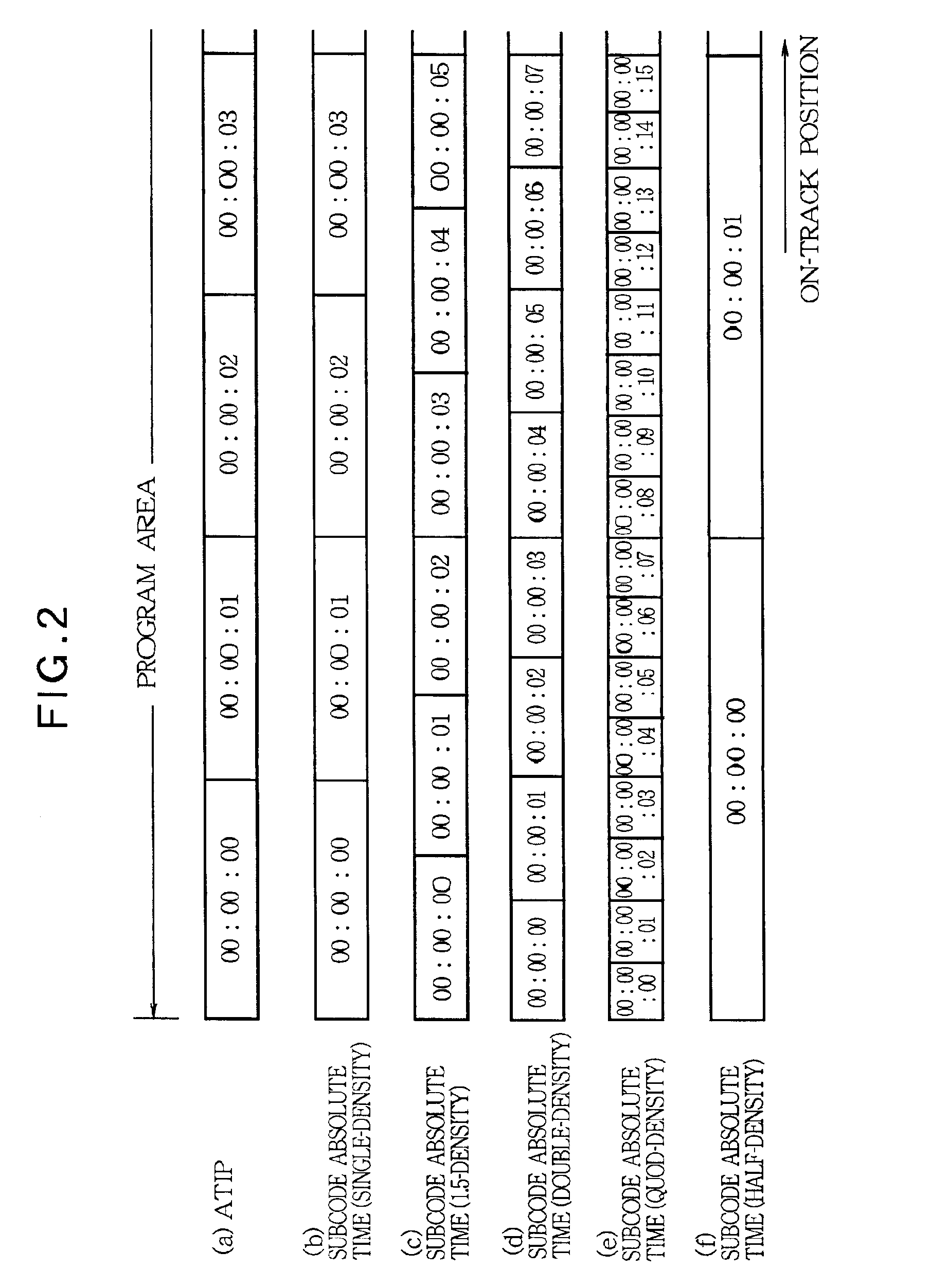
[0012]In a first aspect of the invention, an optical disk recording method records contents information on a track of a recordable optical disk which is previously recorded with first index information in the form of sequentially progressive position information or
time information along the track in a specified format. The optical disk recording method additionally provides the contents information with second index information in the form of position information or
time information which sequentially progresses at a progressing rate differing from that of the position information or
time information previously recorded on the optical disk. According to this optical disk recording method, the contents information is additionally provided with position information or time information which sequentially progresses at a progressing rate differing from that of the position information or time information previously recorded on the optical disk. Because of this, it is possible to
record information with a
recording density differing from specifications of an optical disk to be used, and to provide high-density recording and low-density high-quality recording.
[0013]The second index information in the form of the position information or time information attached to the contents information can be designed to progress at a specified velocity scaling factor with respect to a progressing rate of the first index information in the form of the position information or time information previously recorded on the optical disk. In this case, when the specified velocity scaling factor is greater than 1, high-density recording is implemented. Especially, when the specified velocity scaling factor is an integer, it is possible to sequentially advance and
record the position information or time information at each unit segment obtained by equally dividing the unit segment of the position information or time information previously recorded on an optical disk by that integer. This makes the
record control easy. By contrast, when the specified velocity scaling factor is less than 1, low-density high-quality recording is implemented. Especially, when the specified velocity scaling factor is the reciprocal of an integer, it is possible to sequentially advance and record the position information or time information at each unit segment obtained by multiplying the unit segment of the position information or time information previously recorded on an optical disk by that integer. This makes the record control easy.
[0020]For example, the present invention makes it possible to record data with a specified
linear density as defined in the CD standards along an inner periphery zone of the optical disk, and to record data with a higher
linear density than for the inner periphery zone along an outer periphery zone of the optical disk. In this case, data of the inner periphery side can be reproduced without errors when a conventional optical disk
reproduction apparatus is used for
reproduction. A specific
reproduction apparatus capable of reproducing high-density recording disks can reproduce all information from both of the inner and outer annular zones and therefore can increase a recording capacity compared to the prior art. Further, it is possible to create a disk with
high security by recording data with desired linear densities individually specified for a plurality of recording zones.
[0023]The inventive method is designed to record data such that the recording
linear density gradually changes between adjacent recording zones on the optical disk. Accordingly, it is possible to successively record data on a plurality of recording zones with different recording linear densities without temporarily stopping the operation. This eliminates a seek operation or a setting operation, while shortening the recording time and decreasing the number of recording steps.
[0024]According to a preferred embodiment of the present invention, a recording area on the optical disk is divided into a first zone along the inner periphery and a second zone along the outer periphery. The first zone records data with a first recording linear density as a standard density. The second zone records data with a second recording linear density as a higher density than the standard density. In this case, the first and second zones are each provided with a lead-in area, a program area, and a lead-out area in the order from the top of each zone, and record the data such that the recording linear density gradually changes from the first recording linear density to the second recording linear density between the top of the lead-out area in the first zone and the end of the lead-in area in the second zone. Especially, the data is preferably recorded such that the recording linear density gradually changes from the first recording linear density to the second recording linear density between the top and the end of the lead-out area in the first zone. If a reverse seek moves a reproduction position from the second zone to the first zone during the data reproduction, the aforementioned recording enables smooth signal reproduction, thereby allowing a return to a correct position.
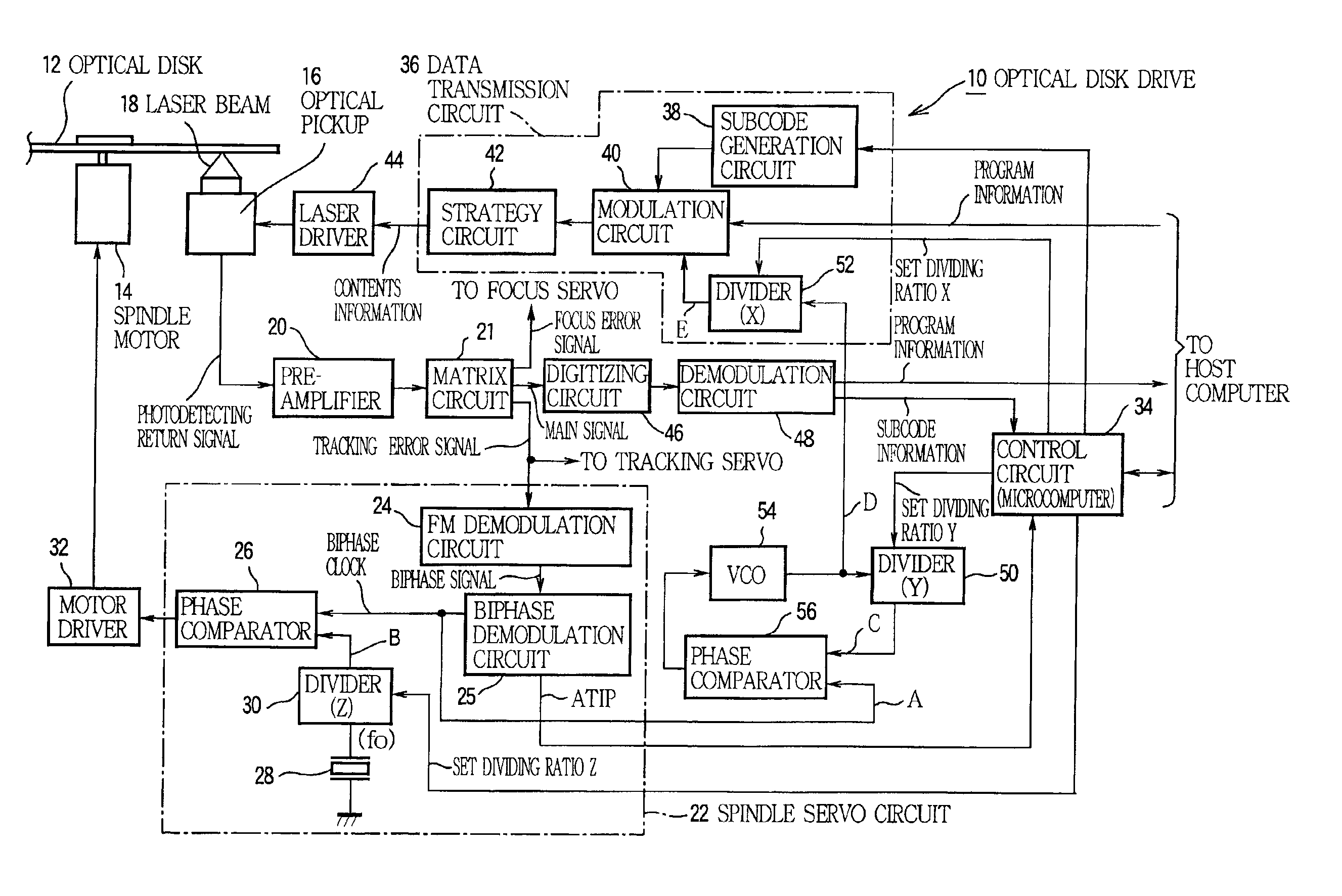
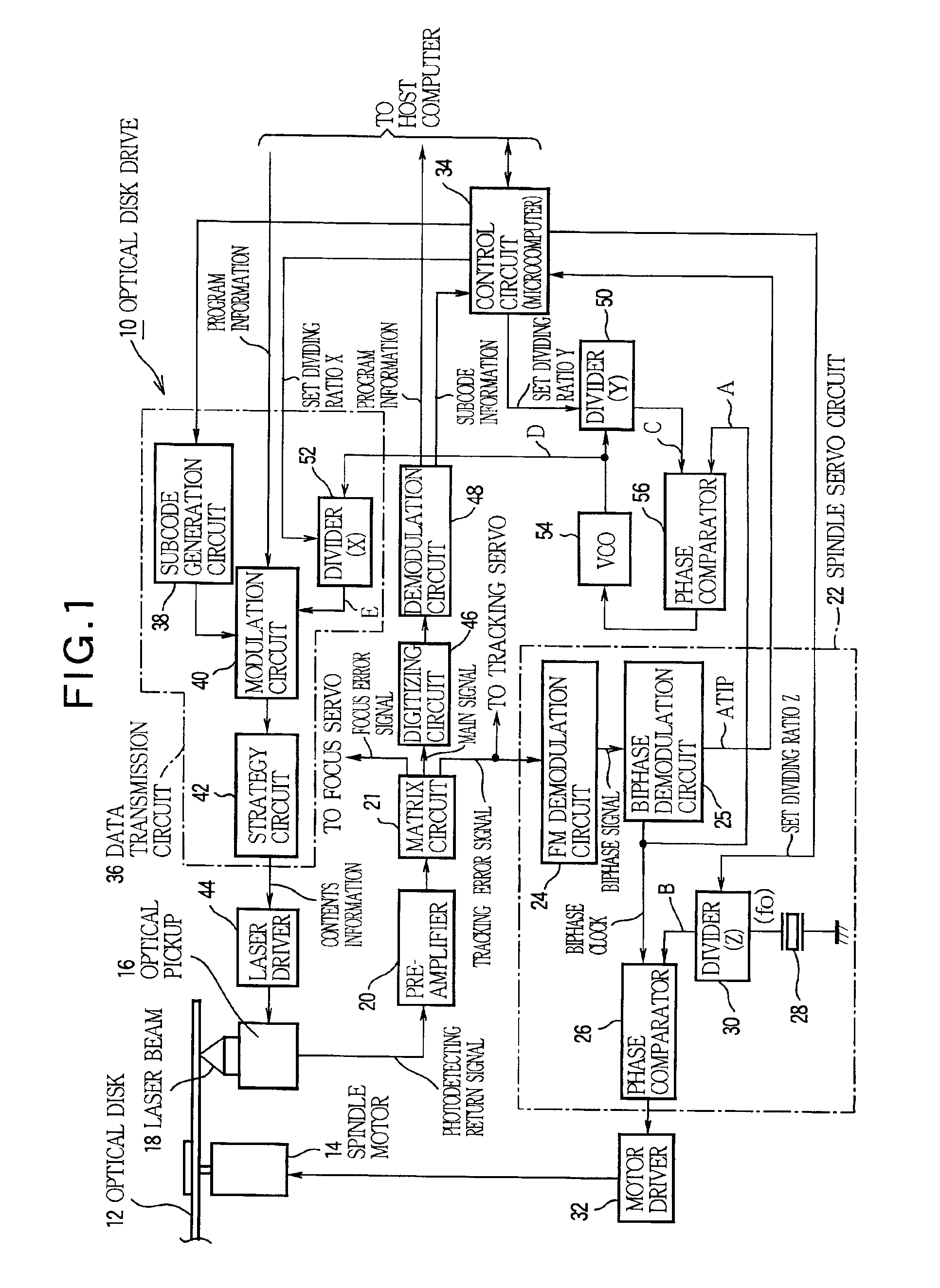
[0025]An optical disk according to the present invention records data based on the aforementioned recording method. Further, an optical disk recording apparatus according to the present invention uses an optical disk which is continuously recorded with a linear density
control signal from the innermost periphery to the outermost periphery with a constant linear density in order to specify a recording linear density of data, divides a recording area of the optical disk into a plurality of recording zones, and records data in the plurality of recording zones using different linear densities. The apparatus is comprised of rotation driving means for rotatively driving the optical disk, a
pickup for reading the linear density
control signal from the optical disk and for recording data on the optical disk, writing clock generation means for recording data based on the linear density
control signal acquired via the
pickup, recording control means for recording data on the optical disk via the
pickup according to a writing clock generated by the writing clock generation means, and linear density control means for controlling a
bit rate of the writing clock relative to a revolution speed of the optical disk such that the recording linear density of the data gradually changes between adjacent recording zones on the optical disk.

