High speed low power 4-2 compressor

a compressor and low power technology, applied in the field of logic circuits, can solve the problems of increasing the complexity of the multiplier circuit, increasing the cost of the circuit, and increasing the number of circuits required

Inactive Publication Date: 2005-06-07
SAMSUNG ELECTRONICS CO LTD
View PDF14 Cites 6 Cited by
  • Summary
  • Abstract
  • Description
  • Claims
  • Application Information

AI Technical Summary

Benefits of technology

[0013]It is therefore an object of the present invention to provide a high-speed low-power 4-2 compressor by reducing the total internal load capacitance and reducing the circuit area and power consumption of the 4-2 compressor.
[0022]The first inverter may comprise a P type transistor and a N type transistor having a current path between a power supply voltage source and an output port of the NOR gate in series, and a control electrode controlled by the first input data ‘a’. The first full-swing means may comprise a P type transistor having a current path between an output port of the first inverter and the output port of the NOR gate, and control electrode controlled by the first input data ‘a’. The first full-swing means may be turned on when the output signal of the NOR gate is the second logic level, and increases the voltage level of the output signal of the first inverter as high as the power supply voltage level.
[0023]The second inverter may comprise a P type transistor and a N type transistor having a current path between a ground voltage source and an output port of the NAND gate in series, and a control electrode controlled by the output of the NOR gate. The second full-swing means may comprise a N type transistor having a current path between an output port of the second inverter and the output port of the NAND gate, and control electrode controlled by the first input data ‘a’. The second full-swing means is preferably turned on when the output signal of the NAND gate is the first logic level, and decreases the voltage level of the output signal of the second inverter as low as the ground voltage level.

Problems solved by technology

However, as technology progresses a user demands increasingly fast data processing systems.
To satisfy the demand, the multiplier circuit grows in complexity, and, as a result, the multiplier occupies an increasingly larger area of a central processing unit (CPU) to be embedded in the data processing system.
Thus, a significant amount of circuit area is required to implement a multiplier for input data of large bit width

Method used


Image

  • High speed low power 4-2 compressor
  • High speed low power 4-2 compressor
  • High speed low power 4-2 compressor

Examples


Embodiment Construction

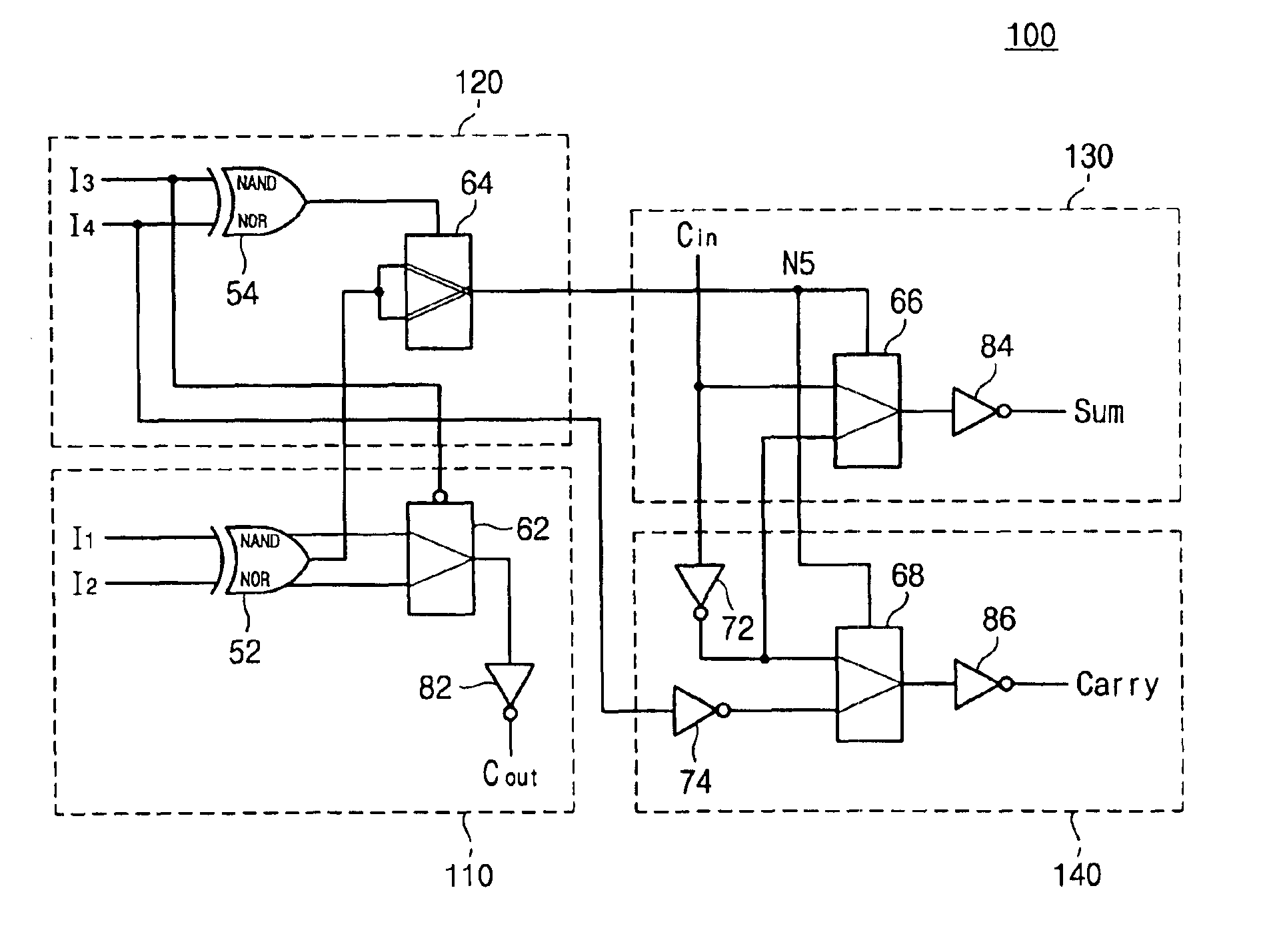
[0035]FIG. 6 is a circuit diagram for illustrating a 4-2 compressor 100 according to a preferred embodiment of the present invention. FIG. 7A is a detailed circuit diagram for illustrating an XOR / XNOR logic circuit shown in FIG. 6, and FIG. 7B is a detailed circuit diagram for illustrating a single railed multiplexer shown in FIG. 6.

[0036]Referring first to FIG. 6, the 4-2 compressor 100 comprises four logic circuits 110, 120, 130 and 140. The first logic circuit 110 generates a NAND / NOR result of externally input first and second data 11 and 12, and an XOR / XNOR result by using the NAND / NOR result, and generates a carry-out bit Cout in response to the NAND / NOR result. The second logic circuit 120 generates a selection signal, in response to the NAND / NOR results from the first logic circuit 110 and externally input third and fourth input data 13 and 14. The third logic circuit 130 generates a sum bit Sum by selecting either a carry-input bit Cin from a previous stage or an inverted c...


PUM


Abstract

A high speed low powered 4-2 compressor according to the present invention performs an XOR / XNOR operation of input data by using a single input type NAND / NOR logic circuit and a dual input type NAND / NOR logic circuit. Thus, delays to generate complementary signals are avoided. In addition, the 4-2 compressor uses a single railed multiplexer instead of a dual railed multiplexer, so that gate drive nodes and internal load capacitance are reduced. As a result, circuit area and power consumption of the 4-2 compressor are reduced.

Description

[0001]This application relies for priority upon Korean Patent Application No. 2000-85542, filed on Dec. 29, 2000, the contents of which are herein incorporated by reference in their entirety.FIELD OF THE INVENTION[0002]The present invention generally relates to a logic circuit and, more particularly, to a 4-2 compressor for a multiplier.BACKGROUND OF THE INVENTION[0003]Multiplication is one of the primary operations in general-purpose microprocessors and special purpose digital signal processors. The speed of the multiplication operation often directly determines how fast the processors are capable of operating. Generally, a multiplier generates plural partial summation results and then sums the partial results to compute a product. The summation performance influences the performance of the multiplier. However, as technology progresses a user demands increasingly fast data processing systems. To satisfy the demand, the multiplier circuit grows in complexity, and, as a result, the m...

Claims


Application Information

Patent Timeline
Patent Type & Authority Patents(United States)
IPC IPC(8): G06F7/50G06F5/06G06F7/52G06F7/48H03K19/00G06F7/38G06F7/60
CPCG06F7/607G06F5/06
Inventor RHEE, YOUNG-CHUL
Owner SAMSUNG ELECTRONICS CO LTD
Why Eureka
Try Eureka