Fluid treatment apparatus

Inactive Publication Date: 2005-06-28
GB ENVIRONMENTAL
View PDF10 Cites 9 Cited by
  • Summary
  • Abstract
  • Description
  • Claims
  • Application Information

AI Technical Summary

Benefits of technology

[0011]In use, the portion of the cleaning means, which is biased against the external surface of the radiation source, is driven around the lamp and at the same time is driven longitudinally of the lamp. This creates a scrubbing action which substantially cleans any slime or othe

Problems solved by technology

Water treatment companies are reluctant to utilize UV sterilizers of the above-mentioned type because they do not effectively treat all of the water.
One reason for this is that slime and other matter, which accumulates on the surface of the lamp submerged in the water, attenuates the UV light so much that micro-organisms which do not come within close proximity of the UV lamp do not receive a dose of UV radiation which is sufficient to kill them.
Furthermore, the main accumulation on the lamp is attributable to the dead carcasses of

Method used


Image

  • Fluid treatment apparatus
  • Fluid treatment apparatus
  • Fluid treatment apparatus

Examples


Embodiment Construction

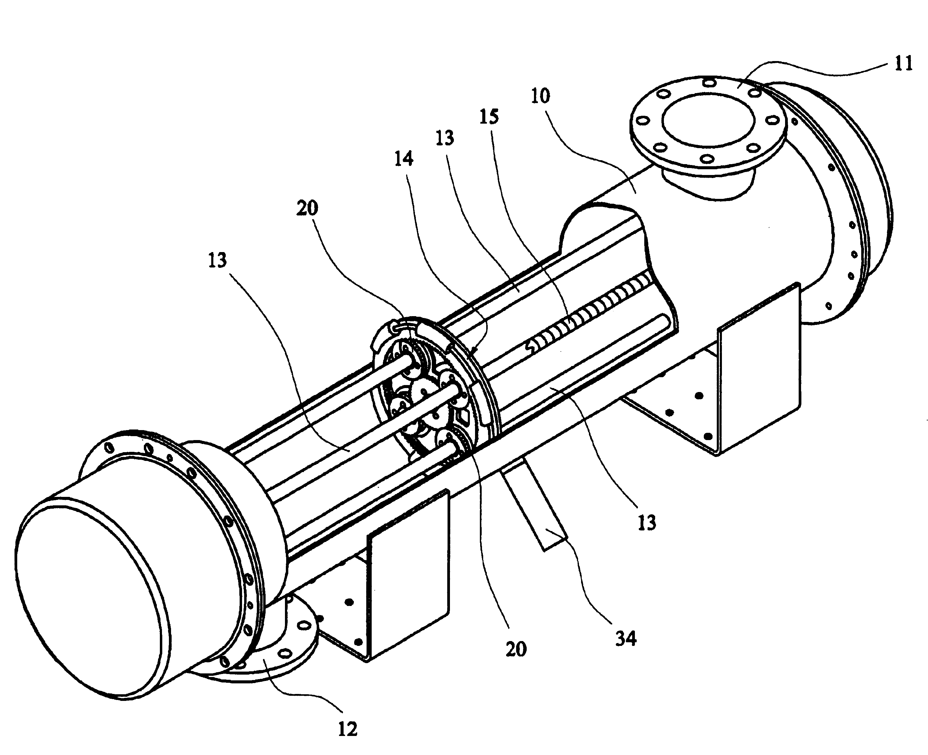
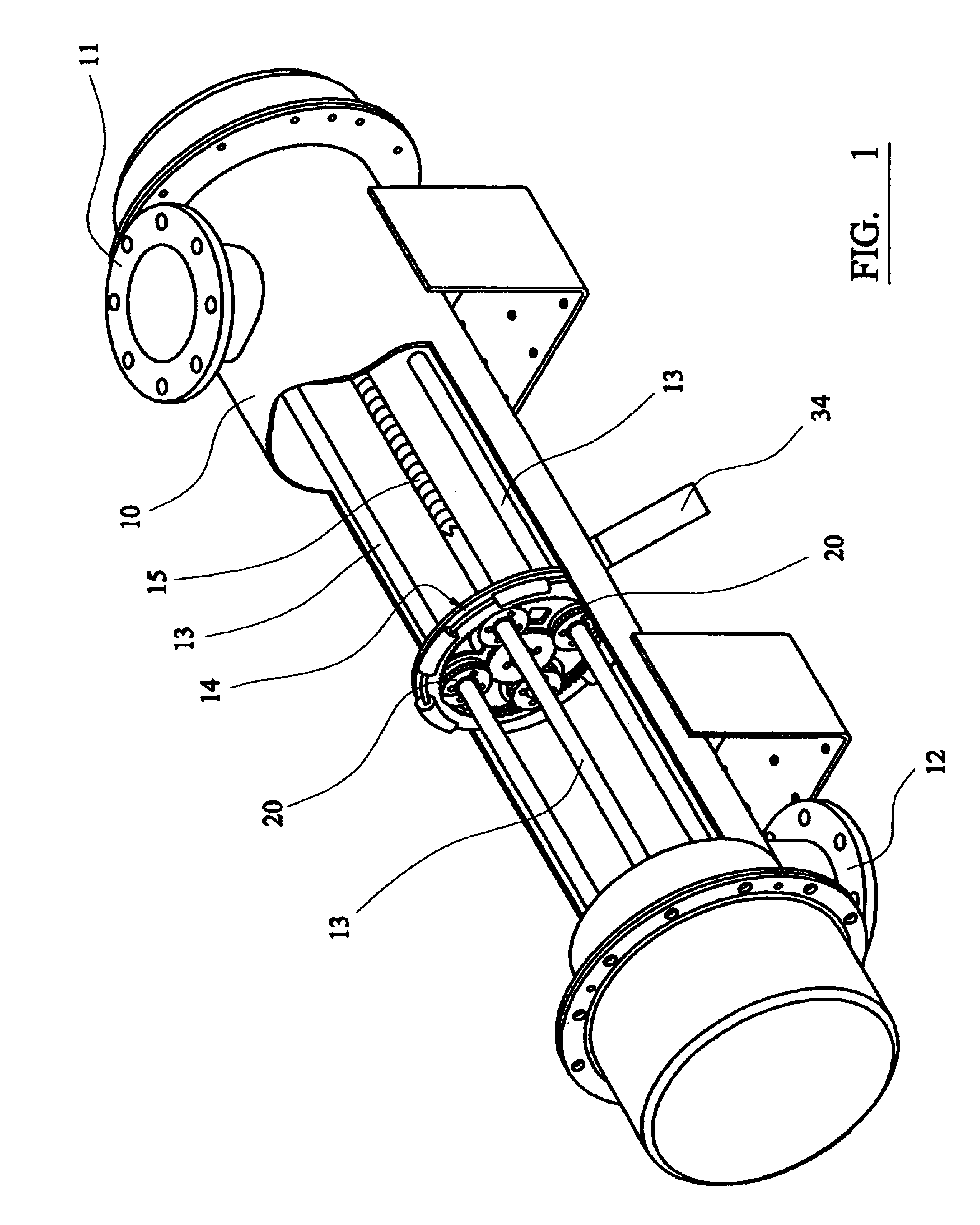
[0044]Referring to FIG. 1 of the drawings there is shown a water treatment apparatus comprising an elongate tubular duct 10 formed of stainless steel and having inlet and outlet ducts 11, 12 mounted at its opposite ends. Four parallel elongate ultra-violet lamps 13 extend along the axis of the duct 10.

[0045]In use, water flows through the duct 10 between the inlet 11 and outlet, where it is irradiated by the UV lamps 13. The lamps 13 illuminate and kill any micro-organisms in the water. However, the effectiveness of the apparatus depends on the dose of radiation received by the micro-organisms.

[0046]In time, slime and other matter, including the carcasses of dead micro-organisms accumulate on the lamps 13, as well as on the internal reflective surface of the duct 10. This accumulation of matter attenuates the UV light and can lead to an insufficient dose of radiation being delivered.

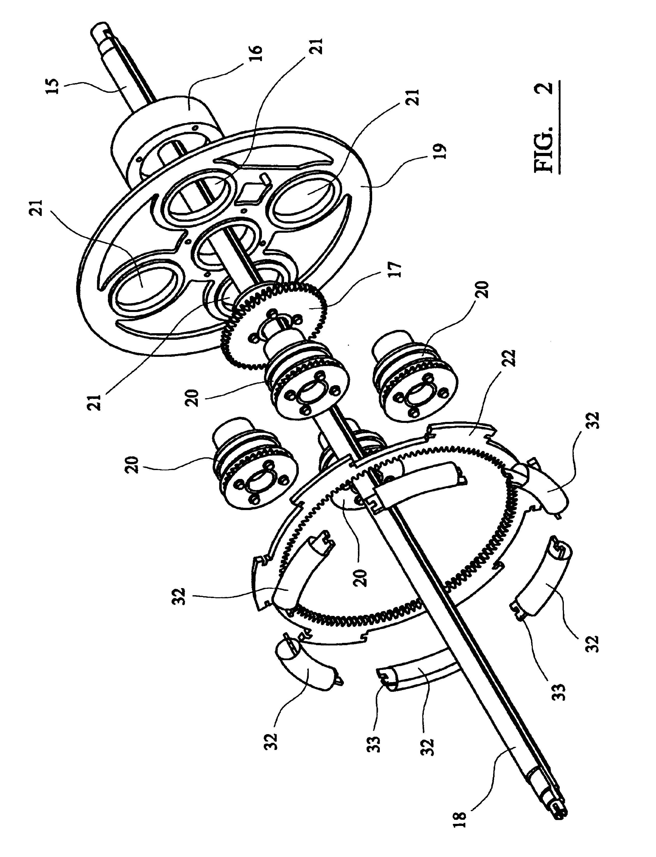
[0047]In order to overcome this problem, and in accordance with this invention, the apparatus further...


PUM


Abstract

A fluid treatment apparatus comprises a plurality of elongate UV lamps 13 mounted in a duct 10 and a cleaning assembly 14 comprising a plurality of cleaning heads 20 which are rotated around respective lamps and are simultaneously driven longitudinally thereof to clean the lamps 13 and the internal surface of the duct 10. The cleaning heads 14 each comprise a plurality of portions 28 of titanium dioxide which are biased against the surface of the respective lamps 13 and which produce hydroxyls and oxygen free radicals in the presence of water and oxygen. Hydroxyls and oxygen free radicals are highly reactive and will break down the cells and molecules of the accumulated material on the lamps.

Description

BACKGROUND OF THE INVENTION[0001]1. Field of the Invention[0002]This invention relates to an apparatus for treating fluids and more particularly but not solely to an apparatus for disinfecting water.[0003]2. Related Background Art[0004]It is well known that high-intensity ultra-violet (UV) light has germicidal properties which can be used to sterilize water. EP-A-0202891 discloses a fluid treatment apparatus which utilizes these germicidal properties, and which comprises an elongate tubular duct having inlet and outlet ports at or adjacent its opposite ends, an elongate UV light source extending along the axis of the duct and a guide vane extending helically along the internal wall of the duct between the input and output ports.[0005]Water treatment companies are reluctant to utilize UV sterilizers of the above-mentioned type because they do not effectively treat all of the water. One reason for this is that slime and other matter, which accumulates on the surface of the lamp submer...

Claims


Application Information

Patent Timeline
IPC IPC(8): A61L2/10C02F1/32C02F1/72
CPCA61L2/10C02F1/325C02F2201/326C02F2201/3227C02F2201/324C02F1/725
Inventor SNOWBALL, MALCOLM ROBERT
Owner GB ENVIRONMENTAL
Why Eureka
Try Eureka