Connection assembly with bayonet locking of the connection elements

Inactive Publication Date: 2016-06-30
RADIALL SA
View PDF16 Cites 9 Cited by
  • Summary
  • Abstract
  • Description
  • Claims
  • Application Information

AI Technical Summary

Benefits of technology

[0023]There is therefore a requirement to improve bayonet locking connection assemblies, notably in order to avoid all risk of a

Problems solved by technology

Patent application EP0660452 discloses a connection assembly with bayonet fixing of a male connector to a panel by means of two removable parts one of which is open and carries a locking lug that lodges in a groove on a projecting part of the panel and the other of which closes the open part in order to prevent access to this locking system, this closing part moreover attaching to the panel, This solution has the disadvantage of a large number of parts that can easily be lost.
This solution firstly has the serious disadvantage of including an additional locking part the shape of which is complicated to produce and that is not robust.
Whatever the efficacy of the known bayonet locking systems, there remains a risk of accidental disassembling thereof during manual manipulations by an operator or manipulations using a tool, more particul

Method used


Image

  • Connection assembly with bayonet locking of the connection elements
  • Connection assembly with bayonet locking of the connection elements
  • Connection assembly with bayonet locking of the connection elements

Examples


Example

[0057]Other advantages and features of the invention will become apparent on reading the following description of one nonlimiting embodiment with reference to the appended drawings, in which:

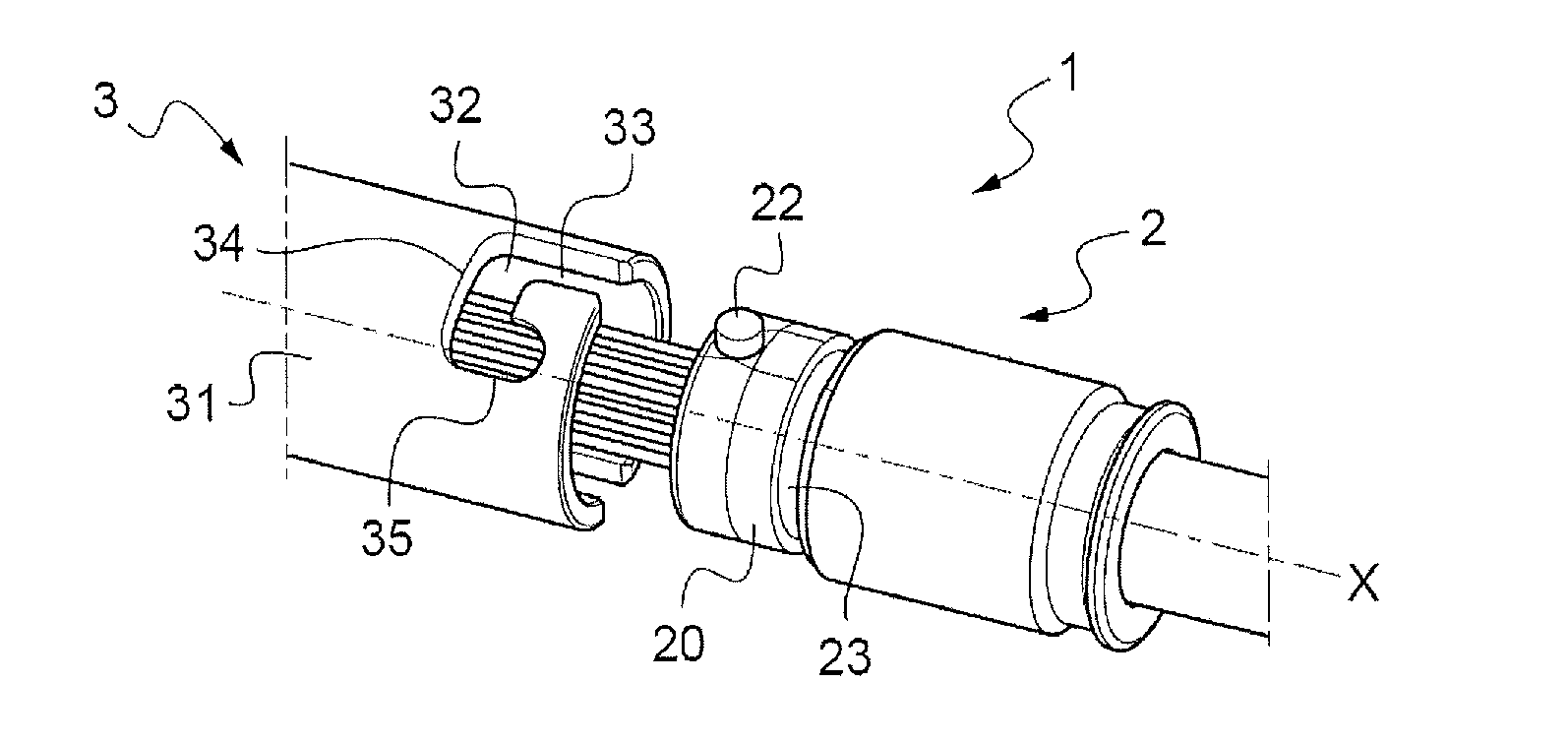
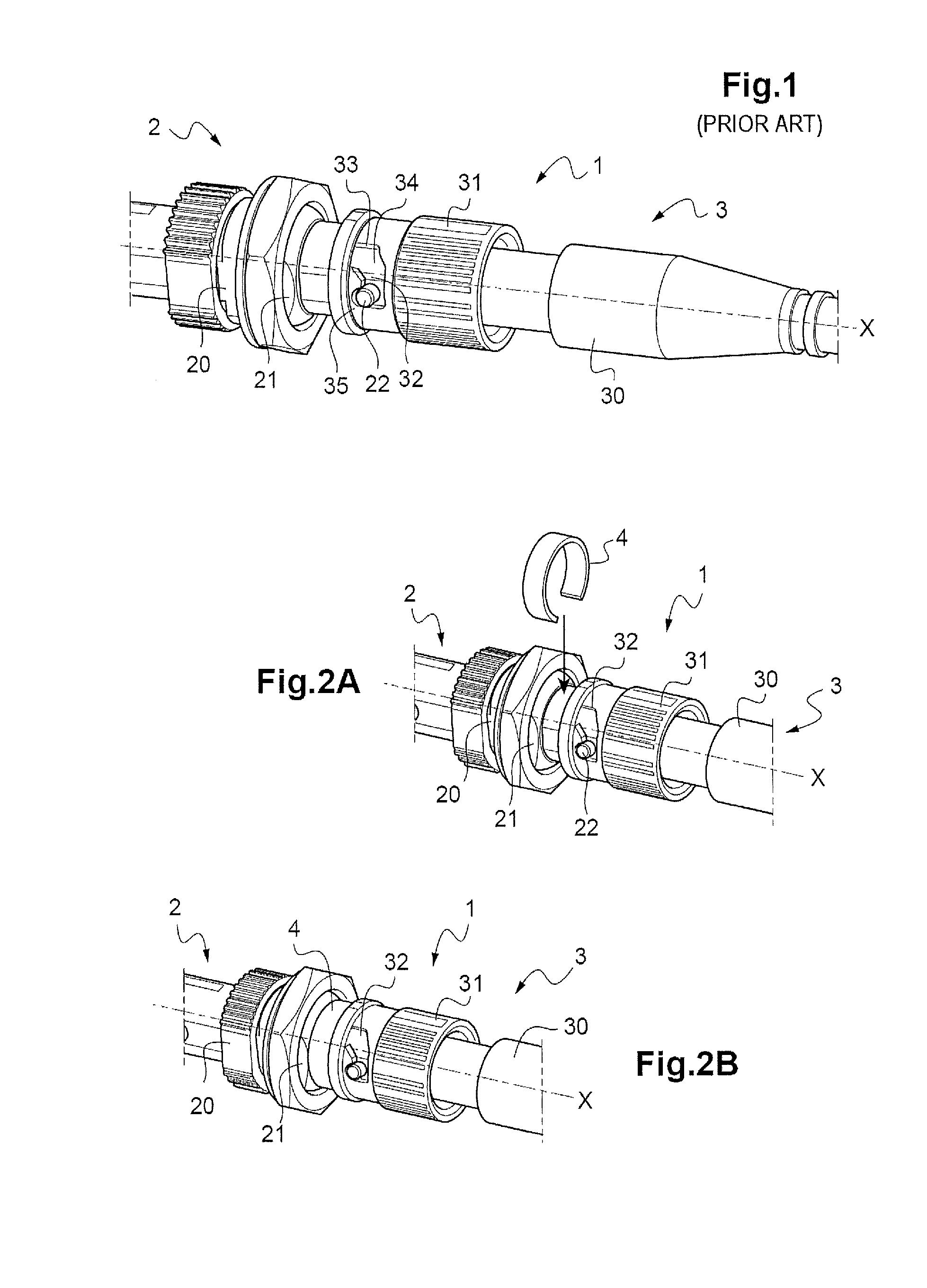
[0058]FIG. 1 is a perspective view of a prior art coaxial connection assembly in its connected and locked configuration,

[0059]FIGS. 2A and 2B are perspective views showing the step of placing an immobilizing part in accordance with a first variant of the invention on an assembly according to FIG. 1,

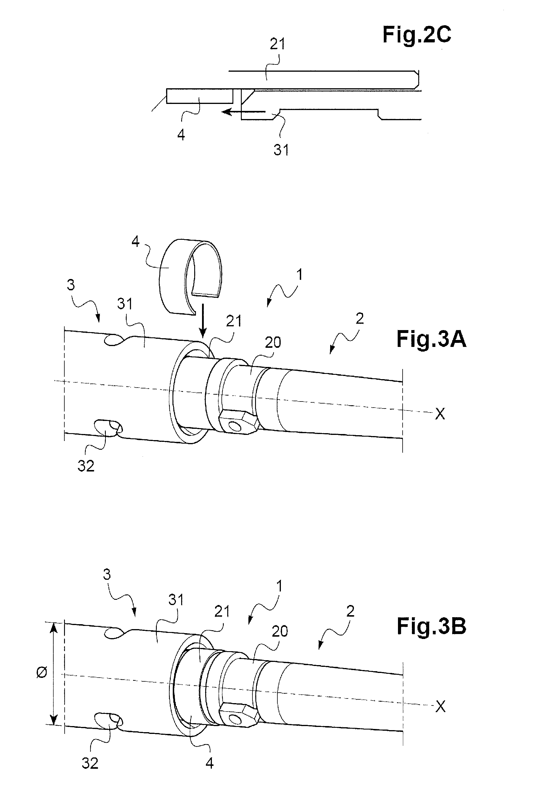
[0060]FIG. 2C is a sectional detail view of FIG. 2B,

[0061]FIGS. 3A and 3B are perspective views showing the step of placing an immobilizing part in accordance with the first variant of the invention on another connection assembly,

[0062]FIGS. 4A to 4F are perspective views showing all of the steps of assembling a connection assembly, including the step of placing an immobilizing part in accordance with a second variant of the invention,

[0063]FIGS. 5 and 5A are respectively a view in longitudinal sectio...


PUM

PropertyMeasurementUnit
Diameteraaaaaaaaaa
Elasticityaaaaaaaaaa

Abstract

A connection assembly with bayonet locking of the connection elements. In accordance with this disclosure, there is provided a part for immobilizing the locking element of the bayonet system against movement in translation in the position of mutual locking, the immobilizing part being removably placed on the body carrying the bayonet lug.

Description

FIELD OF THE INVENTION[0001]The present invention concerns the field of connection assemblies including a first connection element and a second connection element adapted to be locked together by a bayonet locking system.[0002]The invention applies more particularly to optical contact connection assemblies. The invention may for example be applied to a connection assembly with an optical contact element and to its optical connector or to an optical socket.[0003]The invention may be applied in particular to a connection assembly with a plug including at least one contact connected to a cable and an open body inside which the contact or contacts is or are received and with a socket with a plate for fixing it to a panel of a user equipment, the plug and the socket being locked to each other by a bayonet system, for example as described in the patent EP 2239605 B1.[0004]However, the invention is not limited to optical connection assemblies and applies to all those in which the mutual lo...

Claims


Application Information

Patent Timeline
IPC IPC(8): F16B7/20F16B7/04
CPCF16B7/0406F16B7/20G02B6/3891H01R13/625H01R13/6392G02B6/3878
Inventor VALENCIA, LAURENT
Owner RADIALL SA
Why Eureka
Try Eureka