Retaining device for axially retaining a rotor disk flange in a turbomachine

Active Publication Date: 2007-10-11
SN DETUDE & DE CONSTR DE MOTEURS DAVIATION S N E C M A
View PDF3 Cites 9 Cited by
  • Summary
  • Abstract
  • Description
  • Claims
  • Application Information

AI Technical Summary

Benefits of technology

[0004]A main object of the present invention is thus to mitigate such drawbacks by proposing a retaining device

Problems solved by technology

Nevertheless, it presents certain drawbacks.
In particular, in operation, the flange is subjected to axial thrust that runs the risk of tilting the retaining ring outwards from the recess in the rotor disk.
Such tilting of the retaining ring can

Method used


Image

  • Retaining device for axially retaining a rotor disk flange in a turbomachine
  • Retaining device for axially retaining a rotor disk flange in a turbomachine
  • Retaining device for axially retaining a rotor disk flange in a turbomachine

Examples


Example

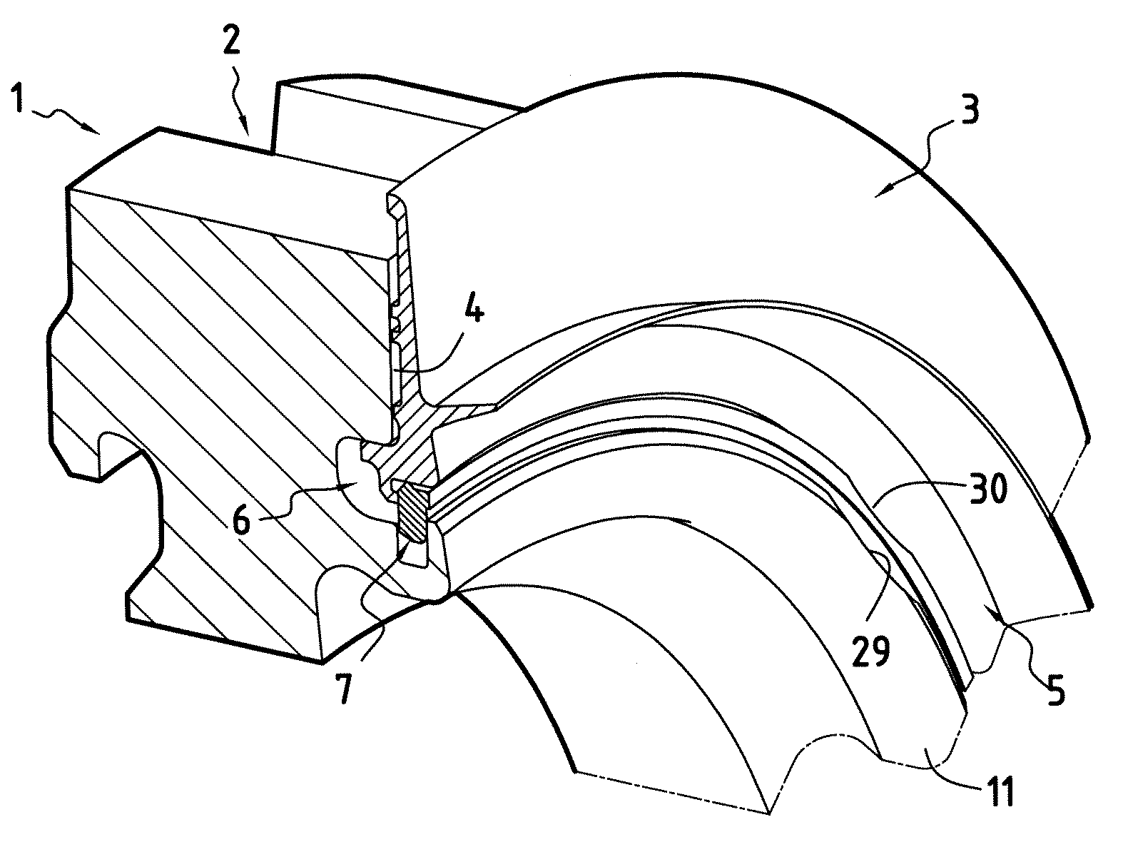
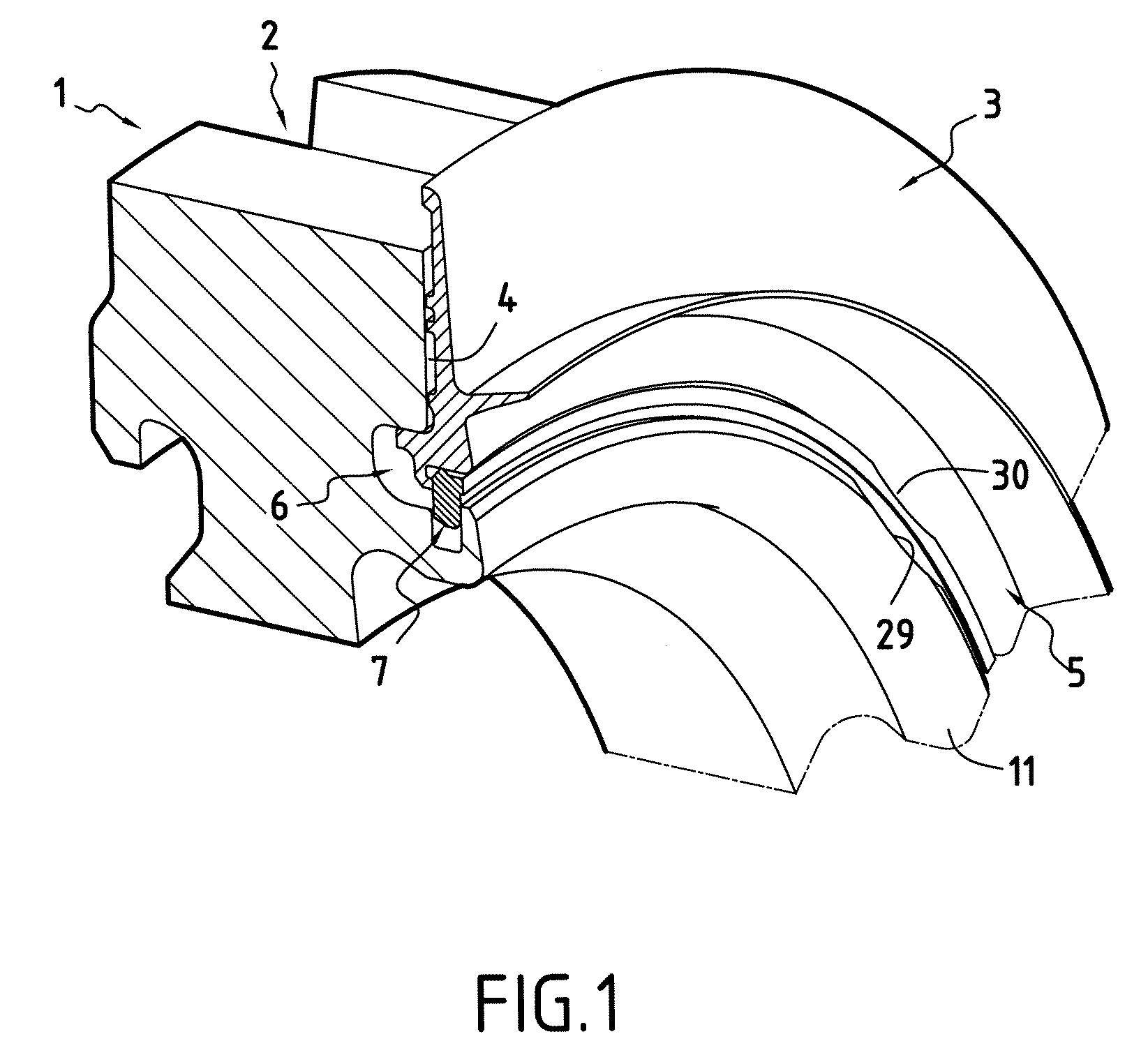
[0014]The figures show a fragment of a turbomachine disk 1, e.g. a rotor disk of a high pressure turbine.

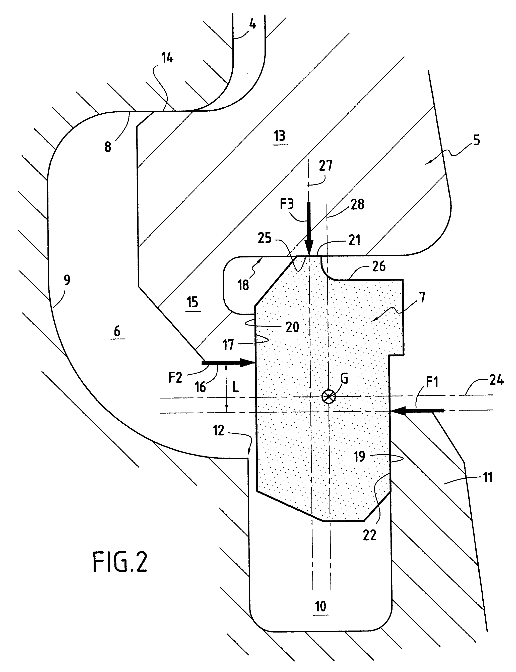
[0015]The disk 1 includes a plurality of substantially axial slots 2 each intended to receive the root of a blade (not shown). An annular flange 3 mounted against a face 4 of the disk serves to prevent the blades from moving axially relative to the disk. A radially inner portion 5 of the flange 3 is received in an annular recess 6 formed in the face 4 of the disk and it is held therein by a retaining ring that is in the form of a split ring 7.

[0016]In the description below, the terms “inner” and “outer” designate a wall or a face respectively closer to or further from the axis of rotation of the disk 1, while the terms “internal” and “external” refer to a wall or a face that is respectively closer to or further from the midplane of the disk.

[0017]As shown in FIG. 2, the annular recess 6 is defined radially outwardly by a wall 8 that is substantially cylindrical and that is connec...


PUM


Abstract

The invention relates to a retention device for axially retaining a rotor disk flange, the device comprising a split annular retaining ring. The ring has an external face bearing against an internal face of the rim, thereby resulting in a first axial force, an internal face bearing against an external face of the root, thereby resulting in a second axial force, the axial forces being radially offset relative to each other, and an outer face bearing against an inner face of the base of the flange, thereby resulting in a radial force. The outer face of the ring presents an annular setback in such a manner that the radial force is situated in a plane that is offset axially relative to a radial plane passing through the center of gravity of the ring so as to obtain mechanical equilibrium between the forces acting on said ring.

Description

BACKGROUND OF THE INVENTION[0001]The present invention relates to a retaining device for axially retaining an annular flange against a radial face of a turbomachine rotor disk.[0002]More precisely, the invention relates to an improvement to the retaining device described in patent application EP 1 498 579 A1 filed by the Applicant. Such a device enables an annular flange to be retained against a radial face of a rotor disk, said disk presenting in the radial face an annular recess that is defined by a plurality of walls, one of which is formed by the internal face of a rim that extends radially outwards, said flange presenting in its radially inner portion an annular base that bears against the radially outer wall of the recess, and a root extending from the base radially inwards into the recess of the disk. According to that invention, the retaining device further comprises a retaining ring constituted by a split ring disposed in the recess of the rotor disk, the retaining ring hav...

Claims


Application Information

Patent Timeline
IPC IPC(8): F01D5/30
CPCF01D5/3015F01D5/027
Inventor GARIN, FABRICEJUDET, MAURICE GUYLANGEVIN, THOMAS
Owner SN DETUDE & DE CONSTR DE MOTEURS DAVIATION S N E C M A
Why Eureka
Try Eureka