Lacrosse head having an articulated member

a technology of lacrosse head and articulated member, which is applied in the field of lacrosse sticks, can solve the problems of maximizing the height of the traditional monolithic rigid sidewall, unable to offer flexibility to the pocket, and unable to keep a ball, so as to achieve better feel for stick handling and ball control, and connection stronger

Inactive Publication Date: 2005-07-12
WM T BURNETT IP
View PDF19 Cites 77 Cited by
  • Summary
  • Abstract
  • Description
  • Claims
  • Application Information

AI Technical Summary

Benefits of technology

[0015]In addressing one or more of the above-mentioned needs, the present invention provides a lacrosse head having at least one of the following features: 1) an articulated member moveably coupled to a rigid lacrosse head frame, which provides flexibility to the frame and / or pocket of the lacrosse head; 2) one or more stiffening members that provide rigidity between a sidewall and the scoop; and 3) a collared male plug connector for joining the head to a hollow lacrosse stick shaft.
[0016]A first embodiment of the present invention provides a lacrosse head having a rigid frame and an articulated member moveably coupled to the rigid frame. The articulated member can be a moveable part of any portion of the frame, such as the sidewalls, the scoop, or the stop. The moveably coupled, articulated member can also be part of any side of the frame, such as the top of a sidewall (corresponding to the front face of the lacrosse head) or the bottom of the scoop (corresponding to the back of the lacrosse head). The articulated member can also be moveably coupled to swing as an extension of the lacrosse head frame (e.g., as a flap on the edge of the frame) or as a moveable interior portion of the frame (e.g., as a moveable cutout within the rigid frame). Finally, the articulated member can include stringing holes to which the pocket threading attaches to provide additional flexibility to the pocket.
[0017]In an exemplary implementation, the articulated member is an articulated sidewall member moveably coupled to a rigid sidewall member of the lacrosse head. The rigid sidewall member is integral with the overall rigid frame of the lacrosse head. By virtue of the moveable coupling (e.g., a hinge), the articulated sidewall member moves (e.g., swings) independently from the rigid sidewall member. The articulated sidewall member includes thread openings to which the pocket of the lacrosse head is strung. In this manner, the movement of the articulated sidewall member increases the overall flexibility of the pocket. This improved flexibility provides a pocket suspension that more effectively dampens the movement of a ball inside the pocket and widens the arc of the pocket swing during cradling.

Problems solved by technology

In a lacrosse game, these dimensional requirements prevent a player from using a stick that unfairly protects the lacrosse ball within a deeper pocket, such that it is more difficult for opponents to check the ball free.
Several drawbacks are associated with conventional lacrosse head designs, relating to stiff pockets that hinder ball control, areas in the head that are susceptible to deformation, wide distances between sidewalls that make it difficult to keep a ball in the pocket, and means of attaching the head to a shaft that prevent a player from positioning his hand on the shaft close to the head.
Unfortunately, maximizing the height of the traditional monolithic rigid sidewall offers no flexibility to the pocket.
The rigid frame of the lacrosse head can make the overall pocket stiff and unforgiving.
A sharp jolt to the stick, as often happens when a player is checked, can cause the stiff pocket to propel the ball out of the lacrosse head.
In addition, the rigid frame limits the degree to which the pocket swings during cradling, and therefore the degree to which a ball in the pocket can move under the frame into a position from which it is more difficult to dislodge.
This transition area therefore becomes a weak portion of the frame, and is vulnerable to bending, twisting, and breaking.
Lacrosse stick designers cannot, however, simply shorten the distance between the sidewalls because of commonly accepted rules mandating the overall width of the head.
The structures in these examples do not, however, improve the rigidity of the lacrosse head in the transition area between the scoop and sidewalls.
This male plug connection, however, provides a relatively weak attachment because the shaft is held onto the male plug by only the friction fit between the components.

Method used


Image

  • Lacrosse head having an articulated member
  • Lacrosse head having an articulated member
  • Lacrosse head having an articulated member

Examples


Embodiment Construction

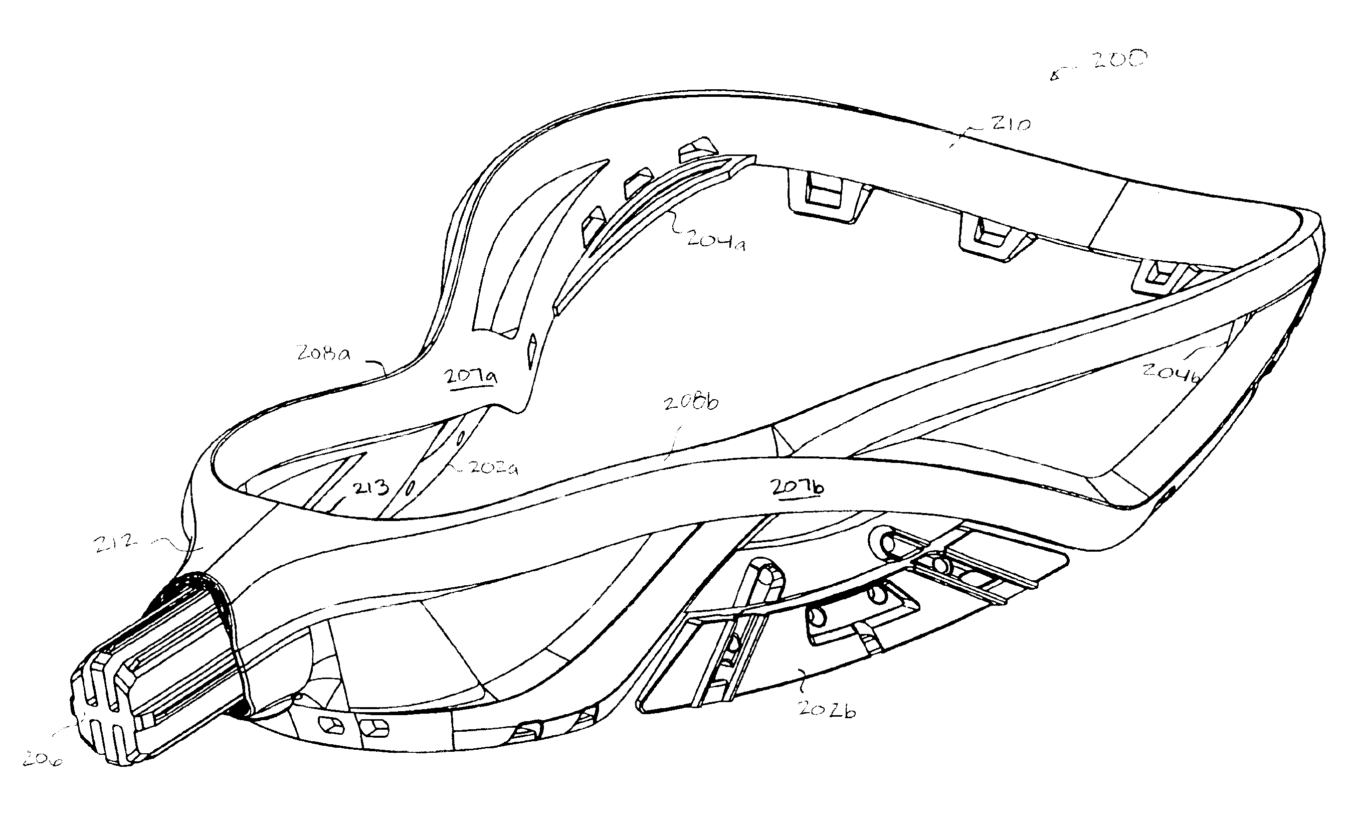
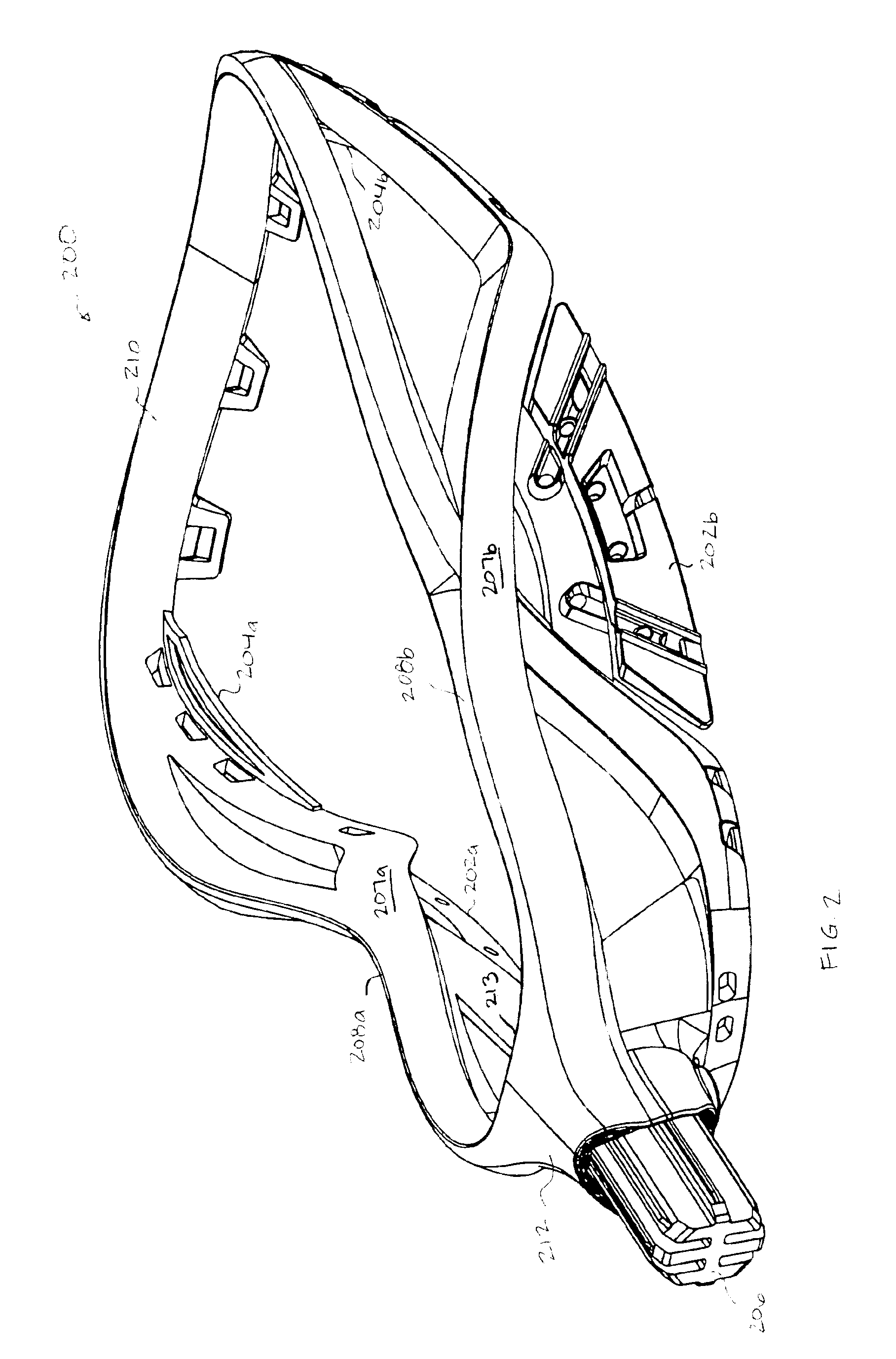
[0063]FIGS. 2-4 illustrate a first exemplary lacrosse head 200, according to an embodiment of the present invention. As shown, lacrosse head 200 includes a scoop 210, sidewalls 208a and 208b connected to scoop 210, and a throat area 212 connected to sidewalls 208a and 208b. Sidewall 208a includes an articulated sidewall member 202a moveably coupled to a sidewall member 207a. Likewise, sidewall 208b includes an articulated sidewall member 202b moveably coupled a sidewall member 207b. A stiffening member 204a is attached to lacrosse head 200 from a point on sidewall 208a to a point on the scoop 210 of lacrosse head 200. Similarly, a stiffening member 204b is attached to lacrosse head 200 from a point on sidewall 208b to a point on scoop 210. Collared male plug 206 is disposed on the throat area 212 of lacrosse head 200.

[0064]FIG. 5A shows an enlarged view of articulated sidewall member 202b, including its three thread holes 502 and four coupling holes 500a-500d. The thread holes 502 r...


PUM


Abstract

A lacrosse head having a frame and an articulated member moveably coupled to the frame. In one embodiment, a lacrosse head includes a stop member; a first sidewall connected to the stop member; a second sidewall connected to the stop member opposite the first sidewall; and a scoop connected to the first sidewall and the second sidewall opposite the stop member, wherein the first sidewall includes a first member integrally connected to the stop member and the scoop, and a second member moveably coupled to the first member. The second member can include pocket thread openings for attaching a pocket to the head. The lacrosse head can also include a stiffening member attached to the scoop and a sidewall of the frame, and a collared male plug for joining the frame to a hollow shaft.

Description

[0001]This application claims the benefit of U.S. Provisional Application No. 60 / 399,722, filed Aug. 1, 2002, which is herein incorporated by referenced in its entiretyBACKGROUND[0002]1. Field of the Invention[0003]The present invention relates generally to lacrosse sticks, and more particularly, to a lacrosse head having an articulated member from which to suspend a pocket. The lacrosse head can further include a stiffening member attached to the scoop and a sidewall, and a connector for joining the head to a hollow lacrosse stick shaft.[0004]2. Background of the Invention[0005]FIG. 1 illustrates a conventional lacrosse stick 100 having a handle 102 shown in dotted lines and a double-wall synthetic head 104. Head 104 comprises a generally V-shaped frame having a juncture 106, sidewalls 108 and 110, a transverse wall (or “scoop”) 112 joining the sidewalls at their ends opposite juncture 106, and a stop member 114 joining sidewalls 108 and 110 at their ends nearest juncture 106. As s...

Claims


Application Information

Patent Timeline
Patent Type & Authority Patents(United States)
IPC IPC(8): A63B59/02A63B59/00
CPCA63B59/02A63B59/0088A63B2243/005A63B59/20A63B60/50A63B2102/14A63B49/035
Inventor KOHLER, DALE W.SHERMAN, KENNETH E.
Owner WM T BURNETT IP
Why Eureka
Try Eureka