Combination layout tool

a layout tool and combination technology, applied in the direction of manufacturing tools, circular curve drawing instruments, instruments, etc., can solve the problems of inaccurate adjustment of squares, and achieve the effect of accurate production of different angles and cuts or layouts

Inactive Publication Date: 2005-07-19
MCBRAYER KEITH
View PDF38 Cites 12 Cited by
  • Summary
  • Abstract
  • Description
  • Claims
  • Application Information

AI Technical Summary

Benefits of technology

[0004]The layout tool of the present invention provides a permanent pattern especially for use on larger building projects that can be used repeatedly to accurately produce different angles and cuts or layouts.
[0005]In accordance with one aspect of the invention, the layout tool of the present invention provides an accurate way of producing certain angles for larger projects, for example, 22½°, 45° and 67½° angles across 24 inch wide projects.
[0006]In accordance with another aspect of the invention, the layout tool can be used to accurately create incremental angles.
[0008]In accordance with another aspect of the invention, the layout tool can be used to effortlessly lay out stairs having for example a 10 inch tread and a 7 inch riser for a 2×12 inch stringer.
[0010]In accordance with another aspect of the invention, the layout tool can be used to accurately create large circles having a diameter for example of between 2 inches and 54 inches in increments for example of 2 inches.

Problems solved by technology

Heretofore, the only layout tools that were available in the marketplace to woodworkers and other craftspeople in crafting the details needed to accomplish a multitude of building projects were small 45° squares and larger adjustable squares that were not very accurate.

Method used


Image

  • Combination layout tool
  • Combination layout tool
  • Combination layout tool

Examples


Embodiment Construction

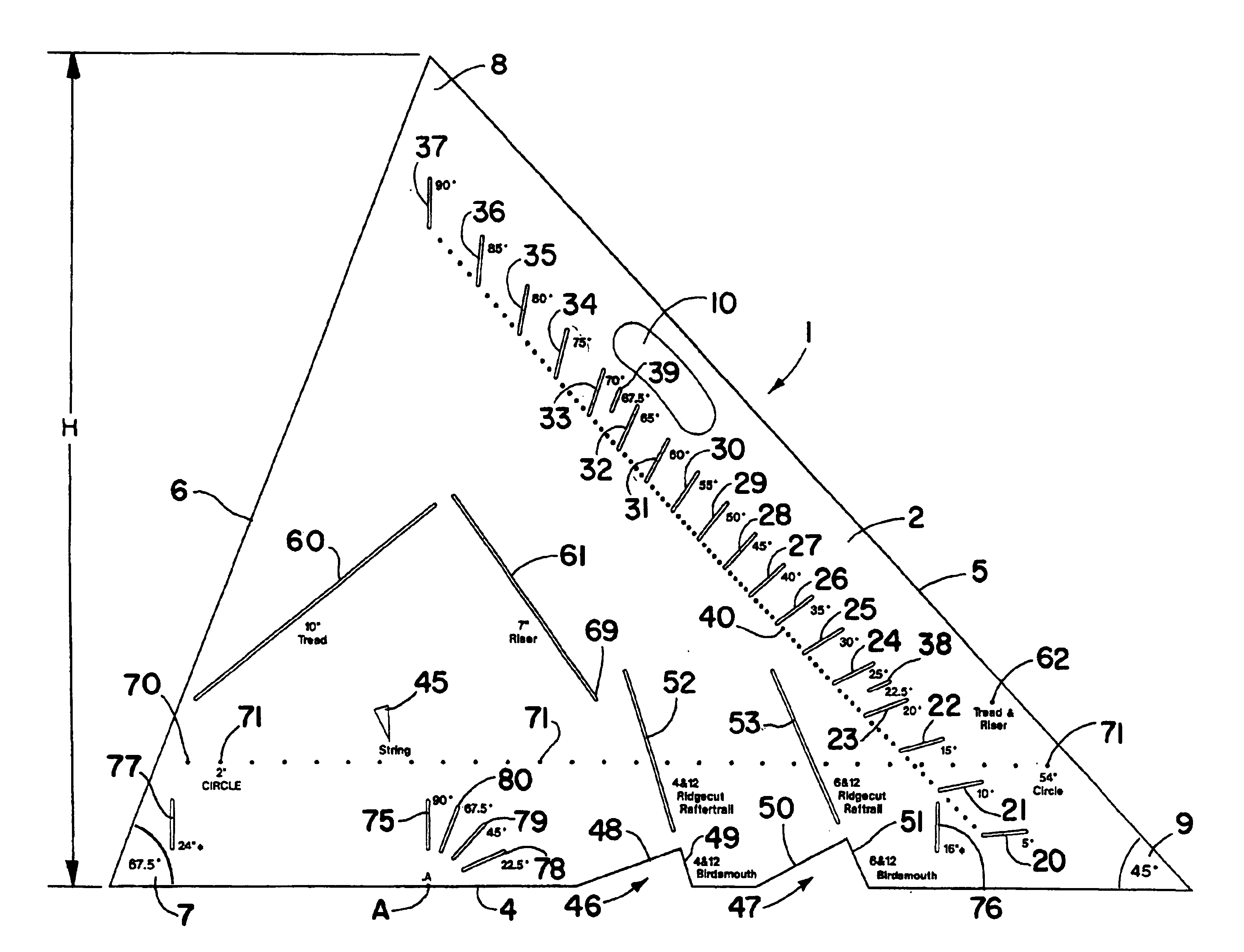
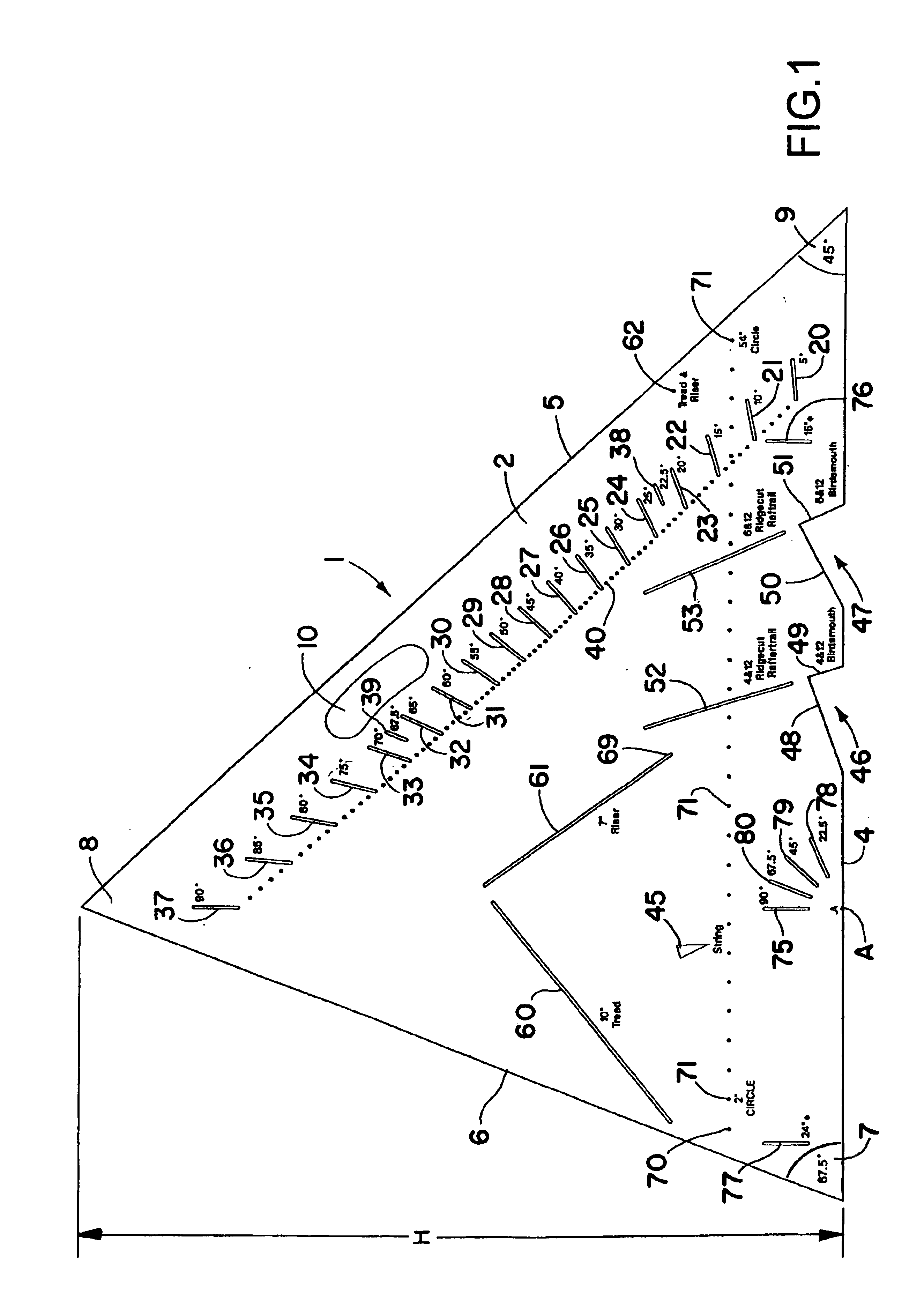
[0023]Referring now in detail to the drawings, and initially to FIG. 1, there is shown one form of combination layout tool 1 in accordance with this invention comprising a triangular shaped member 2 having three side edges 4-6 that intersect at opposite ends to form three corners 7-9. The tool 1 may be made out of a relatively rigid lightweight material such as plastic. In the embodiment shown in FIG. 1, the layout tool has two 67½° angle corners 7, 8 and one 45° corner 9. Also, the layout tool has a perpendicular height H from either 67½° angle corner 7, 8 to the respective opposite side edge 4, 5 of approximately 24 inches. Adjacent one side edge of the tool is an arcuate finger slot 9 to facilitate grasping with one hand for ease of handling.

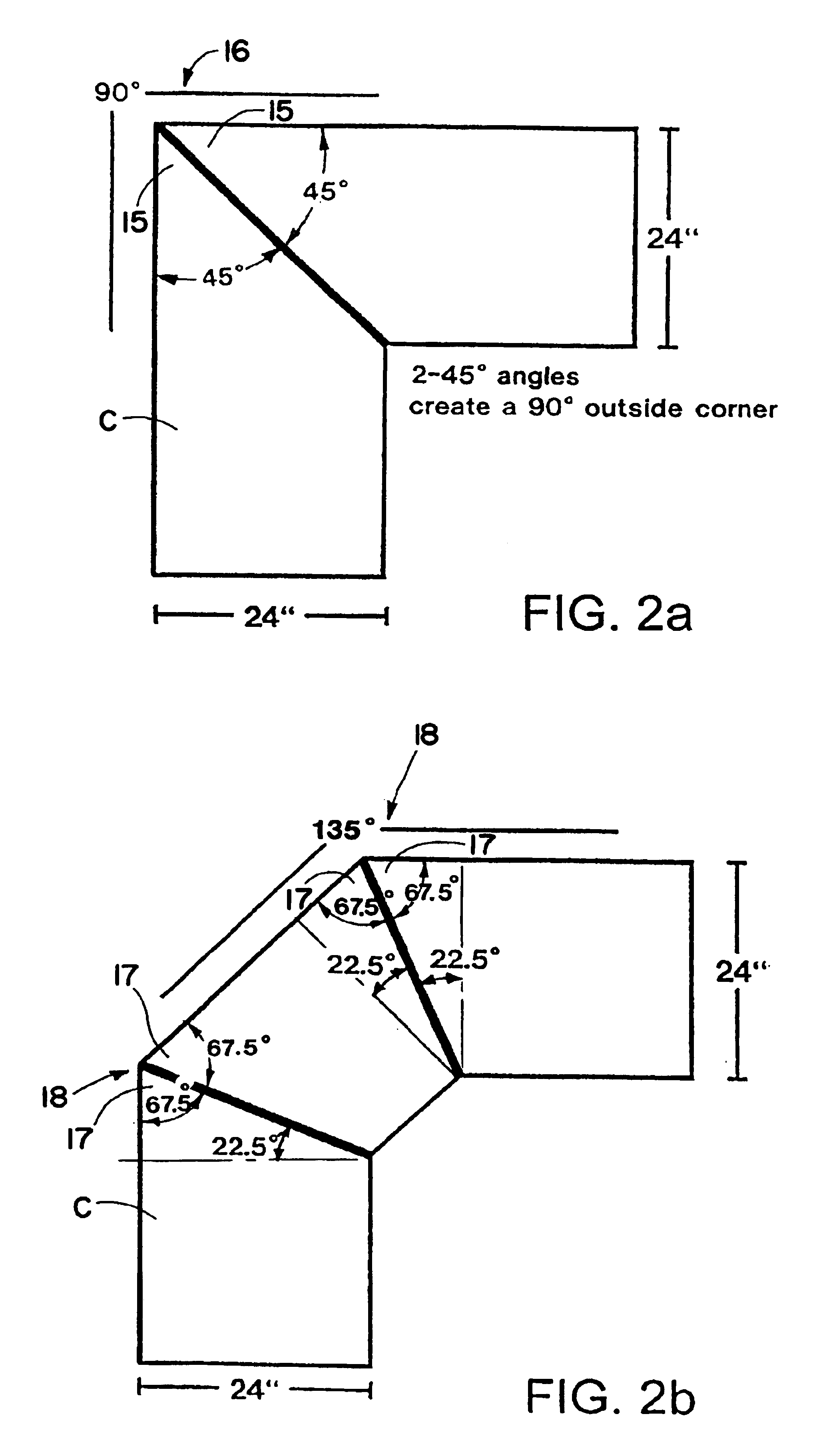
[0024]Such a tool can be used, for example, to accurately produce two 45° miter joints 15 to create a 90° outside corner 16 in a 24 inch deep countertop C as schematically shown in FIG. 2a. Also, such a tool can be used, for example, to accur...


PUM


Abstract

A combination layout tool especially for use in larger building projects that can be used repeatedly to accurately produce different angles and cuts or layouts. The tool is provided with incremental angle slots in radial alignment with a notch in one side edge for producing incremental angles, one or more rafter tail / ridgecut patterns in the side edge, angled slots in alignment with the short side of the patterns, tread and riser slots and an associated tread and riser hole in spaced relation from one another for laying out treads and risers for building stairs, a pivot point receiving hole and a plurality of incrementally spaced marker receiving holes for drawing different diameter circles, and / or one or more stud layout slots in the side edge for making stud layouts for framed walls.

Description

CROSS-REFERENCE TO RELATED APPLICATIONS[0001]This application claims the benefit of U.S. Provisional Application Ser. No. 60 / 243,228, filed Oct. 25, 2000.FIELD OF THE INVENTION[0002]This invention is for a combination layout tool that incorporates a number of features that can be used by woodworkers and other craftspeople, including novices and professionals, in crafting the details needed to accomplish a multitude of building projects.BACKGROUND OF THE INVENTION[0003]Heretofore, the only layout tools that were available in the marketplace to woodworkers and other craftspeople in crafting the details needed to accomplish a multitude of building projects were small 45° squares and larger adjustable squares that were not very accurate.SUMMARY OF THE INVENTION[0004]The layout tool of the present invention provides a permanent pattern especially for use on larger building projects that can be used repeatedly to accurately produce different angles and cuts or layouts.[0005]In accordance ...

Claims


Application Information

Patent Timeline
Patent Type & Authority Patents(United States)
IPC IPC(8): B43L7/00B25H7/00B43L7/033B43L9/00B43L13/00E04F21/26
CPCB25H7/00B43L7/033B43L9/007B43L13/002E04F21/26
Inventor MCBRAYER, KEITH
Owner MCBRAYER KEITH
Why Eureka
Try Eureka