Power amplifier distortion compensation apparatus and method thereof

Inactive Publication Date: 2005-07-26
FUJITSU LTD
View PDF8 Cites 8 Cited by
  • Summary
  • Abstract
  • Description
  • Claims
  • Application Information

AI Technical Summary

Benefits of technology

[0016]frequency characteristic control means for controlling the frequency characteristics of the frequency characteristic compensation filter so that inclination of the phase of the reverse distortion coefficient becomes small, when the power amplifier is connected, by referring to the linear state memory means, using the inclination of the phase of the reverse distortion c

Problems solved by technology

However, if there is a linear error, such as described above, in the power amplifier 18, a problem arises in that the pre-distorter that determines the reverse distortion coefficient by comparing

Method used


Image

  • Power amplifier distortion compensation apparatus and method thereof
  • Power amplifier distortion compensation apparatus and method thereof
  • Power amplifier distortion compensation apparatus and method thereof

Examples


first embodiment

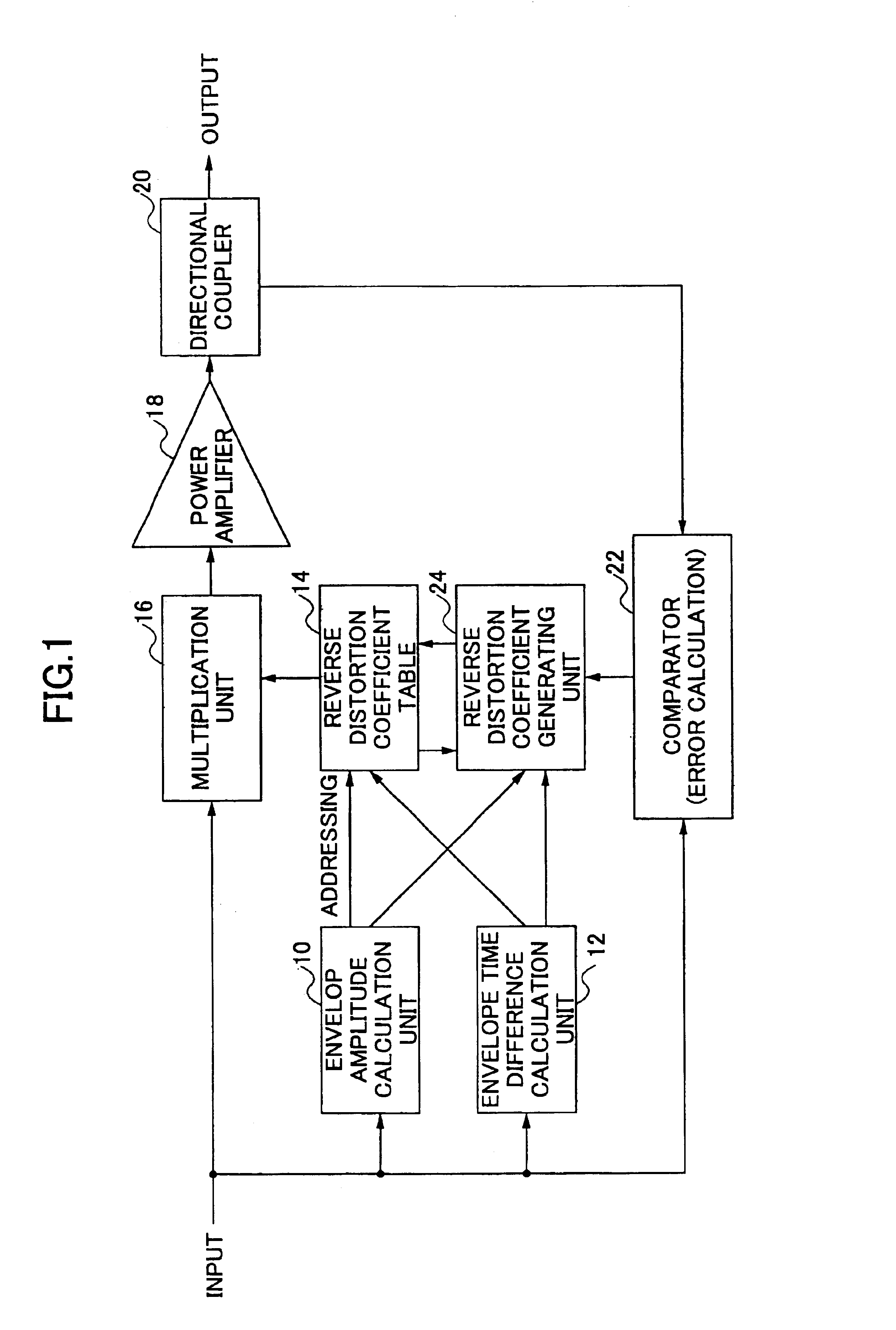
[0034]FIG. 5 is a block diagram of the distortion compensation apparatus of the power amplifier according to the present invention. In reference to FIG. 5, a signal modulated by an orthogonal signal (consisting of an I signal and a Q signal) is supplied to a terminal 30 as an incoming signal, which is distributed to a multiplication circuit 32, an envelope amplitude calculation unit 34, and an envelope time difference calculation unit 36. The envelope amplitude calculation unit 34 calculates envelope amplitude p(t) of the incoming signal, which is then supplied to a reverse distortion coefficient table 38 and a coefficient generating unit 40. The envelope time difference calculation unit 36 calculates a time difference Δp, which is equal to p(t)−p(t−1), of the envelope amplitude, which is supplied to the reverse distortion coefficient table 38 and the coefficient generating unit 40.

[0035]The reverse distortion coefficient table 38 stores combinations of the envelope amplitude p(t) a...

second embodiment

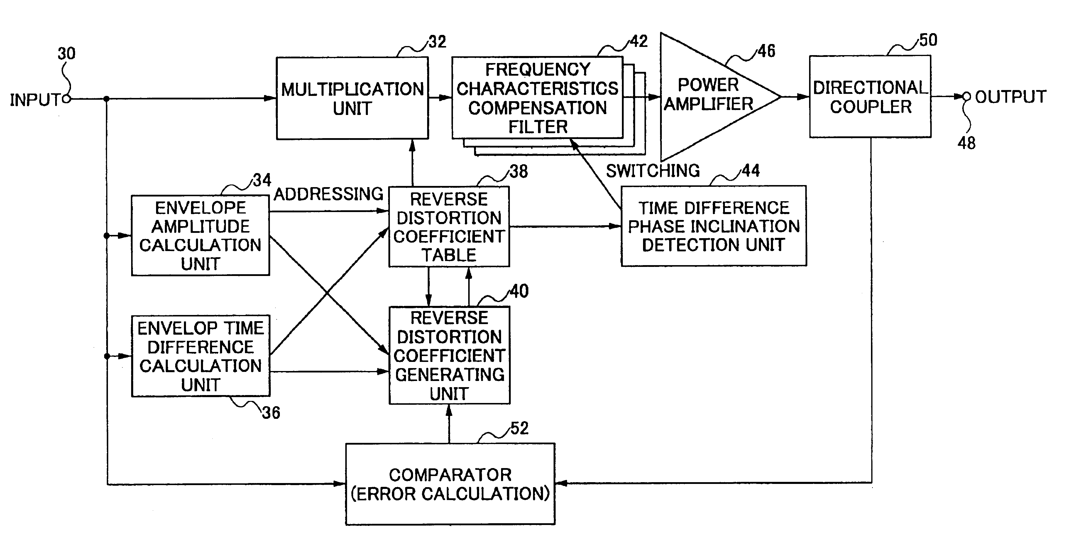
[0044]FIG. 8 is a block diagram of the distortion compensation apparatus of the power amplifier according to the present invention. The same reference marks are given to the portions the same as FIG. 5. In FIG. 8, the signal modulated by an orthogonal signal, consisting of an I signal and a Q signal, is supplied to the terminal 30 as an incoming signal that is distributed to the multiplication circuit 32, the envelope amplitude calculation unit 34, and the envelope time difference calculation unit 36. The envelope amplitude calculation unit 34 calculates envelope amplitude p(t) of the incoming signal, and supplies the computed envelope amplitude p(t) to the reverse distortion coefficient table 38 and the coefficient generating unit 40. The envelope time difference calculation unit 36 calculates a time difference Δp, which is equal to p(t)−p(t−1), of the envelope amplitude, and supplies the time difference to the reverse distortion coefficient table 38 and the coefficient generating ...

third embodiment

[0051]FIG. 9 shows a block diagram of the distortion compensation apparatus of the power amplifier according to the present invention. The same reference marks are given to the same portions as in FIG. 5 and FIG. 8. In FIG. 9, a signal modulated by an orthogonal signal, consisting of an I signal and a Q signal, is supplied to the terminal 30 as an incoming signal, which is provided to the multiplication circuit 32, the envelope amplitude calculation unit 34, and the envelope time difference calculation unit 36. The envelope amplitude calculation unit 34 calculates envelope amplitude P(t) of the incoming signal, and supplies it to the reverse distortion coefficient table 38 and the coefficient generating unit 40. The envelope time difference calculation unit 36 calculates a time difference Δp, which is equal to p(t)−p(t−1), of the envelope amplitude, and supplies it to the reverse distortion coefficient table 38 and the coefficient generating unit 40.

[0052]The reverse distortion coef...


PUM


Abstract

A distortion compensation apparatus and method for a power amplifier enable accurate distortion compensation, even if frequency amplitude deviation and group delay error are present in the power amplifier. A reverse distortion coefficient is read from a reverse distortion coefficient table. A distortion compensation process is performed on an incoming signal using the read reverse distortion coefficient. The distortion compensated signal is amplified and transmitted by the power amplifier, and the reverse distortion coefficient table is updated based on the incoming signal before distortion compensation, and the output signal of the power amplifier. The relation between the phase of the time difference value and the reverse distortion coefficient is obtained from the reverse distortion coefficient corresponding to a linear operation domain of the power amplifier. A frequency characteristic of a frequency characteristic compensation filter, to which the distortion compensated signal is supplied, is set such that inclination of the phase of the reverse distortion coefficient becomes small, thereby accurate distortion compensation can be performed even if frequency amplitude deviation is present in the power amplifier.

Description

BACKGROUND OF THE INVENTION[0001]1. Field of the Invention[0002]The present invention generally relates to an apparatus and a method of distortion compensation for a power amplifier, and especially relates to the apparatus and the method of distortion compensation for the power amplifier used by radio base stations of a cellular phone system, digital broadcasting, and the like.[0003]2. Description of the Related Art[0004]As a technique for reducing distortion of a transmission power amplifier used by radio base stations of a cellular phone system, digital broadcasting, and the like, a pre-distorter has been used. For example, a pre-distorter proposed by JP,54-140856,A suppresses distortion of a power amplifier by applying a reverse distortion coefficient to the power amplifier according to envelope amplitude of a source signal to be transmitted. Characteristics of the reverse distortion are determined by obtaining a difference between the source signal to be transmitted and the sign...

Claims


Application Information

Patent Timeline
IPC IPC(8): H03F1/32H03F3/24
CPCH03F1/3247
Inventor MANIWA, TORU
Owner FUJITSU LTD
Why Eureka
Try Eureka