An AGV Chassis Structure Adaptable to Ground Deformation
An adaptive, ground-based technology, applied in motor vehicles, transportation and packaging, etc., can solve the problems of large chassis shaking, high manufacturing cost, and suspension of driving wheels, and achieve the effect of AGV running smoothly, simple and compact structure, and reducing wear and tear
- Summary
- Abstract
- Description
- Claims
- Application Information
AI Technical Summary
Problems solved by technology
Method used
Image
Examples
Embodiment 1
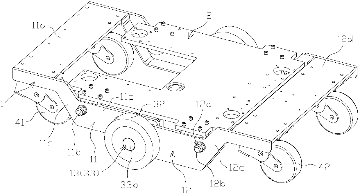
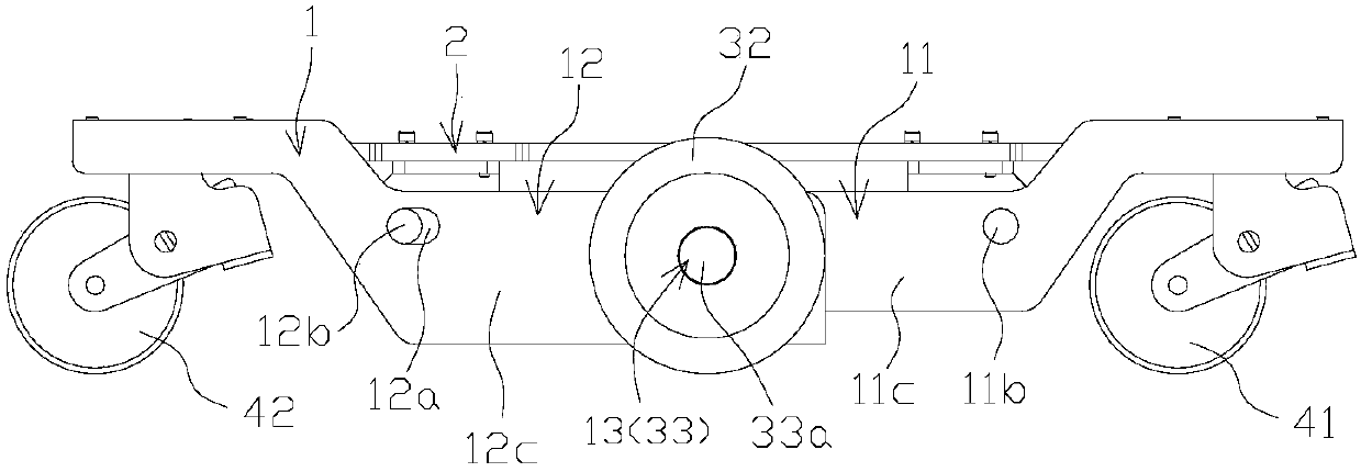
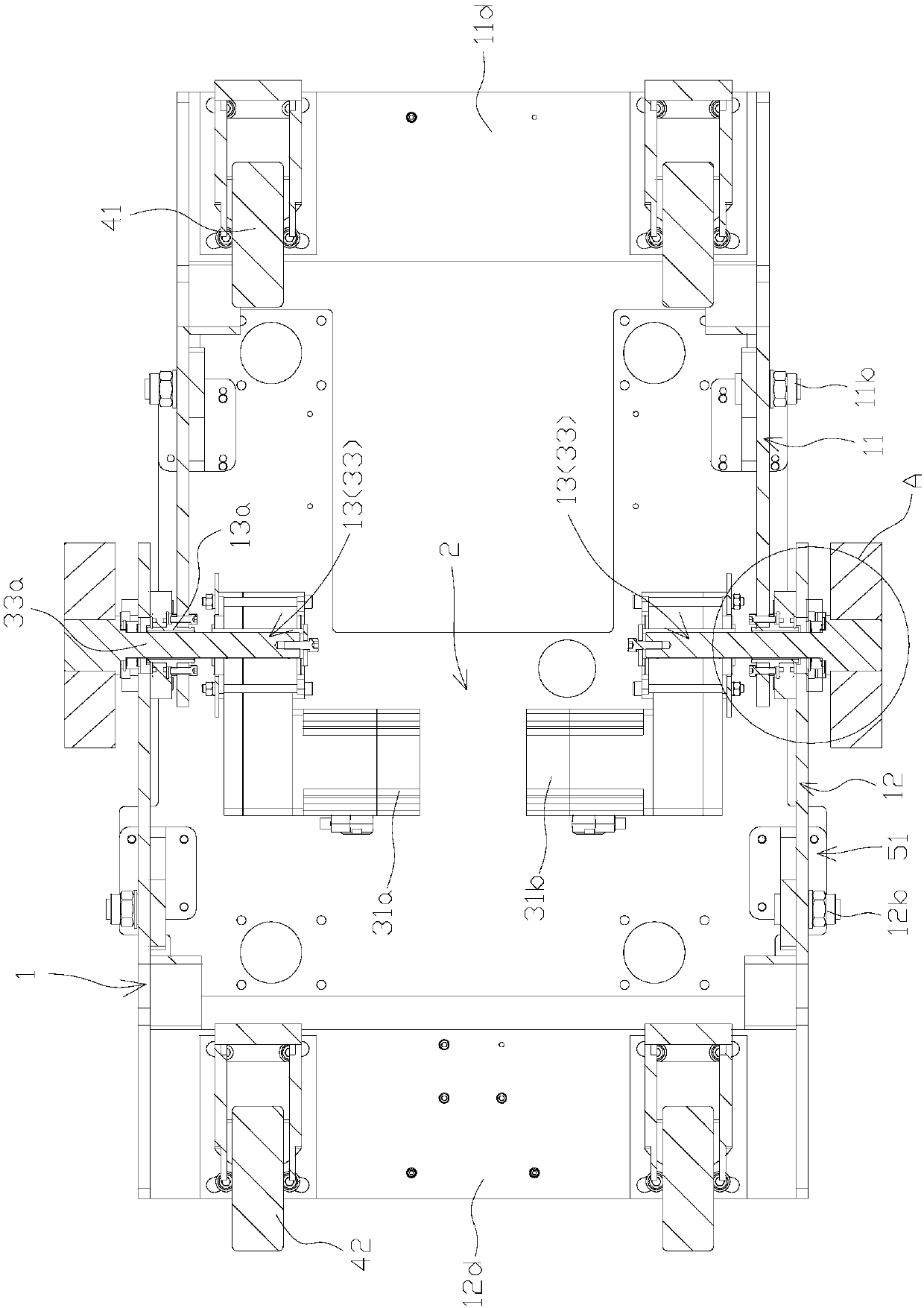
[0020] Embodiment one: see Figure 1 to Figure 5 , an AGV chassis structure that can adapt to ground deformation, including a frame, a driving device and a load-carrying wheel, the frame includes a movable frame 1 and a load-carrying frame 2, and the movable frame 1 includes a first movable frame 11. The second movable frame 12, the inner end of the first movable frame 11 and the inner end of the second movable frame 12 are hinged through the hinge shaft 13, and the carrying frame 2 is arranged on the first movable frame 12. On movable vehicle frame 11 and the second movable vehicle frame 12; Described driving device comprises drive motor, drive shaft 33 and drive wheel 32, and described drive motor is arranged on described movable vehicle frame 1, and described drive shaft 33 is hinged with The shaft 13 is arranged to be coaxially connected, and the drive motor drives the drive wheel 32 through the drive shaft 33; the load wheel includes a first load wheel 41 and a second loa...
Embodiment 2
[0027] Embodiment 2: (not shown in the figure of this embodiment) The difference between this embodiment and Embodiment 1 lies in the difference in the arrangement of the drive shaft and the hinge shaft. The hinge shaft includes a first hinge shaft and a second hinge shaft. The drive shaft includes a first drive shaft and a second drive shaft, the drive motor includes a first drive motor and a second drive motor, and the first hinge shaft and the second hinge shaft are respectively arranged on the left and right sides of the movable frame. side, the inner end of the first hinge shaft is connected to the outer end of the first drive shaft, the inner end of the second hinge shaft is connected to the outer end of the second drive shaft, and the inner end of the first drive shaft is connected to the The first drive motor is connected, the inner end of the second drive shaft is connected with the second drive motor, and the outer end of the first hinged shaft and the outer end of th...
Embodiment 3
[0029] Embodiment 3: (not shown in the figure of this embodiment) The difference between this embodiment and Embodiment 1 is that: the first drive shaft and the first hinge shaft of this embodiment are arranged as an integrated structure, and the second drive shaft and the second hinge shaft The shaft is arranged in an integrated structure, and this arrangement can realize the functions of the hinge shaft and the drive shaft at the same time. This setting method has a simple and compact structure, convenient installation and disassembly, and low manufacturing cost.
PUM
 Abstract
Description
Claims
Application Information
 - R&D
- Intellectual Property
- Life Sciences
- Materials
- Tech Scout
- Unparalleled Data Quality
- Higher Quality Content
- 60% Fewer Hallucinations
Browse by: Latest US Patents, China's latest patents, Technical Efficacy Thesaurus, Application Domain, Technology Topic, Popular Technical Reports.
© 2025 PatSnap. All rights reserved.Legal|Privacy policy|Modern Slavery Act Transparency Statement|Sitemap|About US| Contact US: help@patsnap.com


