System in a vehicle and a heavy vehicle

a technology for systems and vehicles, applied in the direction of electric propulsion mounting, transportation and packaging, jet propulsion mounting, etc., can solve the problems of unfavorable transmission, unfavorable transmission, and increased transmission costs, so as to reduce the distance between the engine and the differential, reduce the transmission vibration, and reduce the transmission vibration

Inactive Publication Date: 2010-02-04
VOLVO LASTVAGNAR AB
View PDF2 Cites 2 Cited by
  • Summary
  • Abstract
  • Description
  • Claims
  • Application Information

AI Technical Summary

Benefits of technology

[0011]An advantage of the present invention is that it can accommodate alignment differences between the engine and differential or that it can provide a possibility to reduce the distance between the engine and the differential without major redesign of the vehicle geometry.
[0012]These and other aspects of the invention will be apparent from and elucidated with reference to the embodiments described hereinafter.
[0013]It is also desirable to provide a heavy vehicle, in which vehicle drive line vibrations is counteracted or decreased relative to corresponding prior art heavy vehicles.
[0014]By the provision of a drive unit which is inclined by being pivoted about an axis whereby the drive unit forms an angle relative to the longitudinal geometrical axis, wherein the pivot axis is situated in a intersectional point between the longitudinal geometrical axis and a longitudinal center axis of the drive unit, and the intersectional point is situated in a position within the extension of the drive unit, it has surprisingly been proved in tests that a relatively small inclination of the drive unit can contribute to important benefits with respect to power transmission and decreased drive line vibrations.
[0015]Inclination angles in the size of 1° can decrease the vibrations to a substantial extent. The inclination angle is preferably in the interval from 0.05 to 1.5 degrees, and more preferably in the interval from 0.25 to 1.2 degrees.
[0016]The pivot axis is preferably substantially vertical so as to incline the drive unit in a substantially horizontal plane. The invention is particularly useful in a vehicle which comprises a propeller shaft connected to the drive unit, wherein the drive unit is inclined so as to compensate for an inclination of the propeller shaft relative to the longitudinal geometrical axis, since the propeller shaft extending between the drive unit and a differential often has a connecting position to the differential which position is arranged with an lateral offset relative to the longitudinal geometrical axis, and a lateral offset relative to the connecting point between the drive unit and the propeller shaft.

Problems solved by technology

A truck is often heavy and large, for example weighing several thousand kilograms and has a powerful engine for driving the wheels.
During certain unfavorable conditions the high power output transferred by the driveline may cause undesired vibrations of the drive line.
Drive line vibration problems may arise when the drive line is assembled with components having dimensions which are in the outer ranges of the component tolerances allowed.
Due to the inclination of the propeller shaft vibrations may arise.
Furthermore, for different length legislations on different markets, for instance, it is desired to decrease the wheel base of heavy vehicles which in turn may increase the vibration problems due to the fact that the inclination angle of the propeller shaft is increased when using a shorter wheel base together with a given differential offset.

Method used


Image

  • System in a vehicle and a heavy vehicle
  • System in a vehicle and a heavy vehicle
  • System in a vehicle and a heavy vehicle

Examples


Embodiment Construction

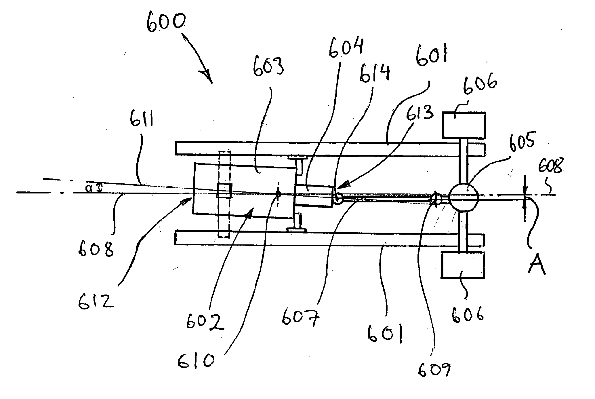
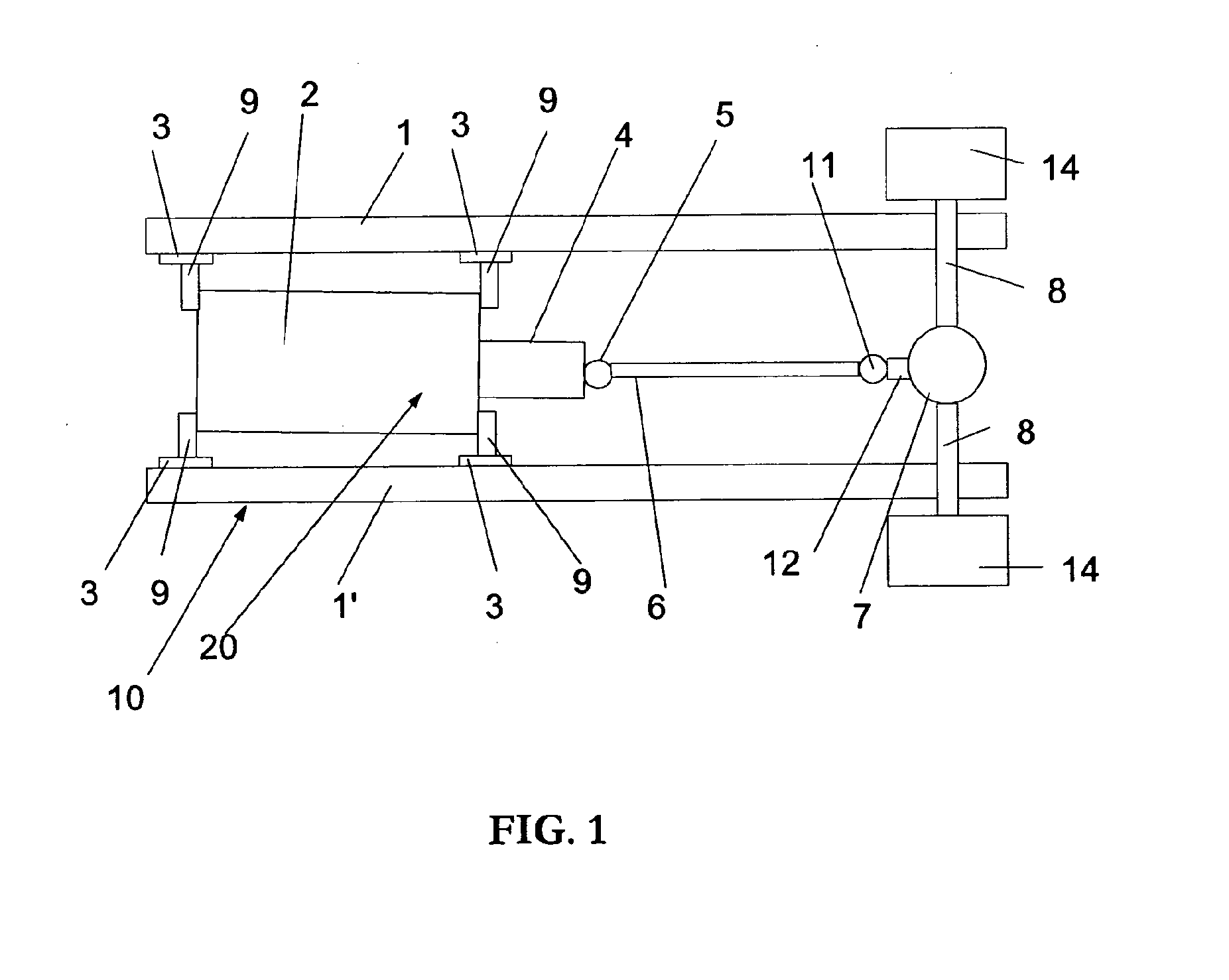
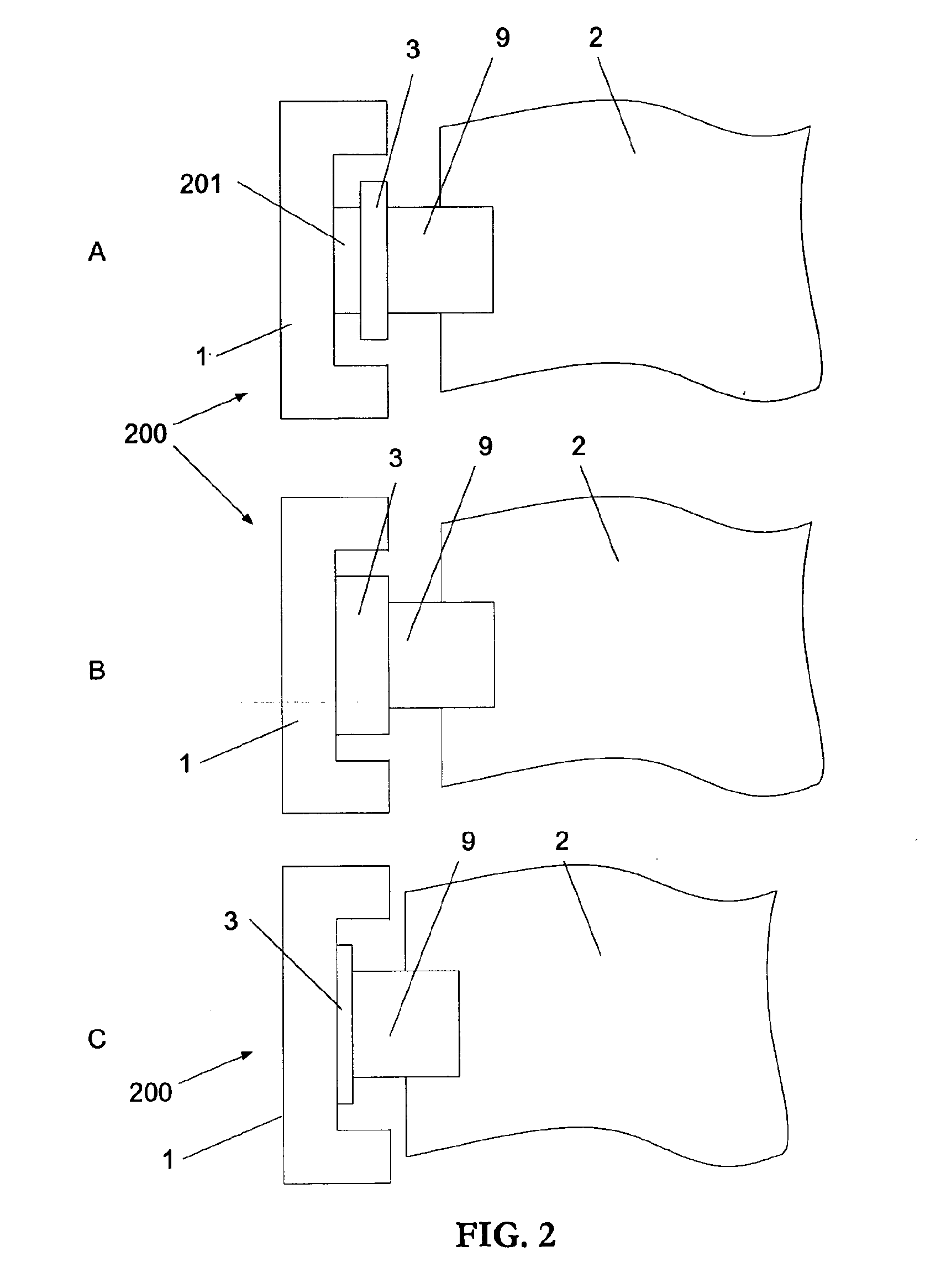
[0025]In FIG. 1, the reference numeral 10 generally denotes a frame of a commercial vehicle. The frame 10 is composed of two U-profile longitudinal side members 1, 1′ united by a plurality of cross members (not shown). An engine 2 is mounted together with a gear box 4 on the frame 1 and 1′ by engine supports each comprising an engine bearer 9 and engine cushion 3. The engine and gearbox together form an engine / gearbox assembly 20. A universal joint 5 is mounted on the gearbox 4 and a propeller shaft 6 transmits power from the engine / gearbox assembly 20 to a differential 7 via a second universal joint 11. The differential 7 distributes the engine power to each driving wheel 14 via respective drive shafts 8. The engine 2, gearbox 4, propeller shaft 6, universal joints 5, 11, and differential 7 together form a power generating and transmission system. Other parts may be used in relation to the power transmission system, for instance a propeller shaft 6 bearing (not shown) for guiding t...


PUM


Abstract

A heavy vehicle includes a drive unit arranged substantially along a longitudinal geometrical axis of the vehicle. The drive unit is inclined by being pivoted about an axis whereby the drive unit forms an angle relative to the longitudinal geometrical axis. The pivot axis is situated in an intersectional point between the longitudinal geometrical axis and a longitudinal center axis of the drive unit, and the intersectional point is situated in a position within the extension of the drive unit.

Description

BACKGROUND AND SUMMARY[0001]The present invention relates to a system in a vehicle, and a heavy vehicle comprising a drive unit arranged substantially along a longitudinal geometrical axis of the vehicle.[0002]A heavy vehicle, such as a truck or a bus, comprises a power transmission system or in other words a drive line for transferring power from an engine to driving wheels of the vehicle. Usually, the drive line comprises a drive unit, i.e. an engine and a gear box, and a propeller shaft and a differential. The drive line is a well balanced optimized system in order to provide power in a safe manner and with low vibrations transferred to the vehicle.[0003]A truck is often heavy and large, for example weighing several thousand kilograms and has a powerful engine for driving the wheels. During certain unfavorable conditions the high power output transferred by the driveline may cause undesired vibrations of the drive line. Drive line vibration problems may arise when the drive line ...

Claims


Application Information

Patent Timeline
Patent Type & Authority Applications(United States)
IPC IPC(8): B60K5/00
CPCB60K5/02B60K17/00B60K5/12B60K5/00B60K17/24F16H57/02
Inventor GUSTAVSSON, MIKAELHENSTROM, JOHNANDREASON, TOMAS
Owner VOLVO LASTVAGNAR AB
Why Eureka
Try Eureka