
Flag support assembly

a technology of support assembly and flag, which is applied in the direction of machine support, instruments, other domestic objects, etc., can solve the problems of flag/banner/sign rump, wrinkle, disorientation, etc., and achieve the effect of splicing parts, and reducing the number of splicing parts

Inactive Publication Date: 2005-08-02
STAATS ROBERT A +2
View PDF14 Cites 50 Cited by
  • Summary
  • Abstract
  • Description
  • Claims
  • Application Information

AI Technical Summary

Benefits of technology

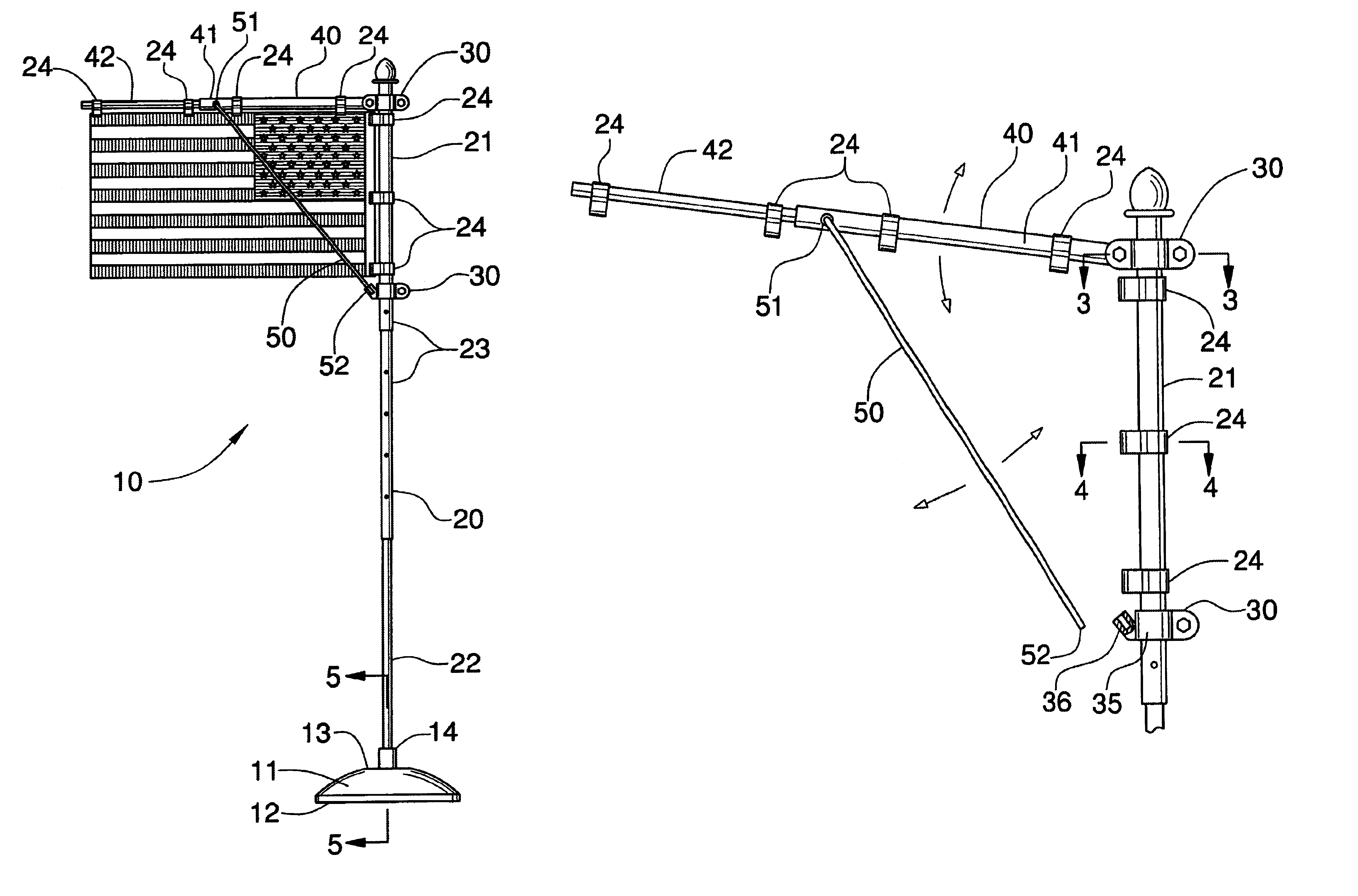
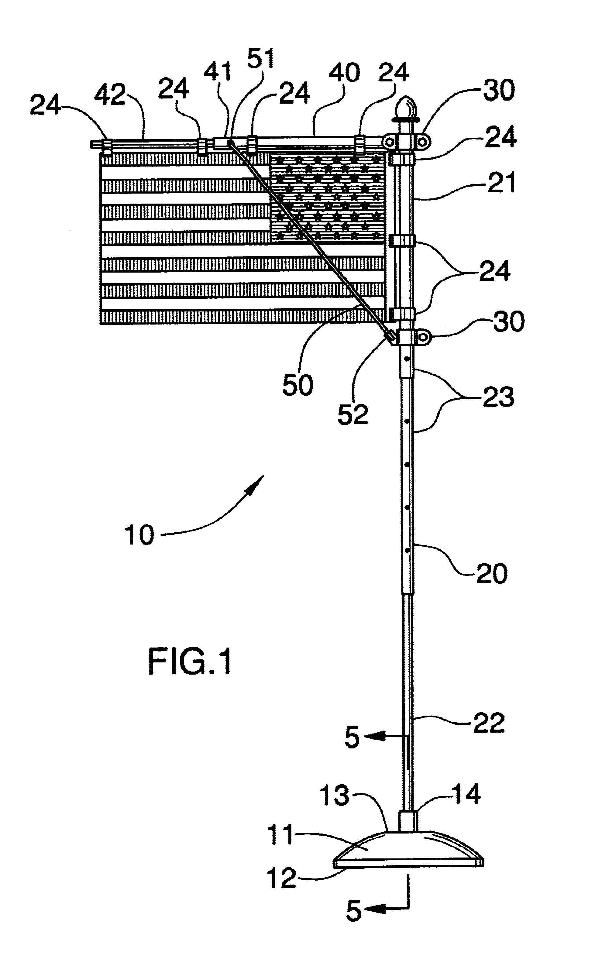
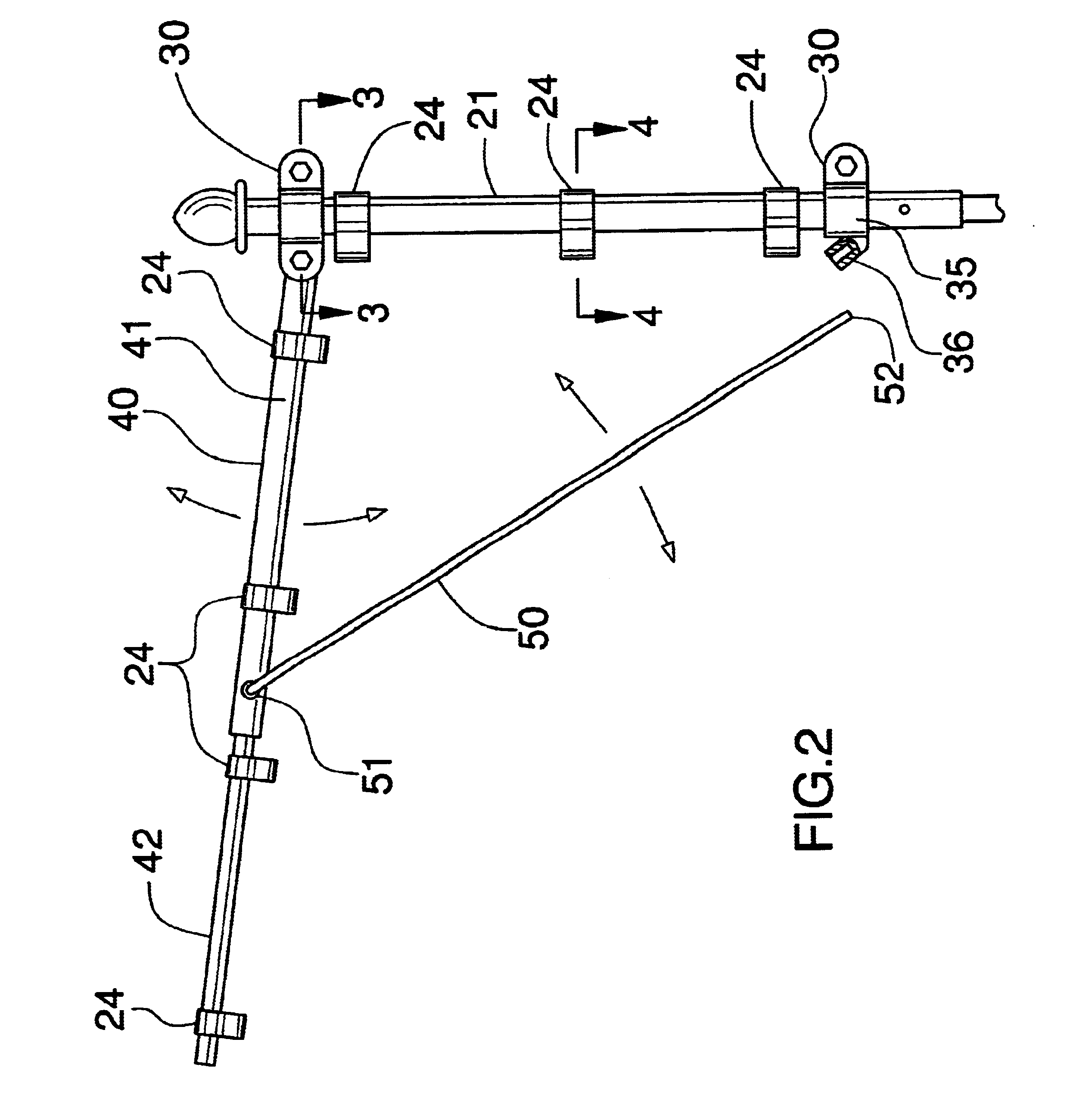
[0011]In view of the foregoing background, it is therefore an object of the present invention to provide an assembly for maintaining flags in a taut, fully extended position. These and other objects, features, and advantages of the invention are provided by a flag support assembly including a base having a substantially planar bottom portion and an upper portion integral therewith. Such an upper portion has an opening disposed medially thereof and includes a threaded inner surface. The assembly further includes an elongated flagpole having an upper portion and a threaded lower portion telescopically connected thereto and removably engageable with the opening so that the flagpole can be maintained at a substantially vertical position.

Problems solved by technology

Problems occur when wind and other natural forces cause the flag / banner / sign to become rumpled, wrinkled, disoriented, and otherwise unattractively displayed about its support structure.

Method used


Image

  • Flag support assembly
  • Flag support assembly
  • Flag support assembly

Examples


Embodiment Construction

[0022]The present invention will now be described more fully hereinafter with reference to the accompanying drawings, in which a preferred embodiment of the invention is shown. This invention may, however, be embodied in many different forms and should not be construed as limited to the embodiments set forth herein. Rather, this embodiment is provided so that this application will be thorough and complete, and will fully convey the true scope of the invention to those skilled in the art.

[0023]The assembly of this invention is referred to generally in FIGS. 1-5 by the reference numeral 10 and is intended to provide a flag support assembly. It should be understood that the assembly 10 may be used to support many different types of flags, pennants, and other signs and banners and should not be limited to supporting only flags.

[0024]The assembly 10 includes a base 11 having a substantially planar bottom portion 12 and an upper portion 13 integral therewith and having an opening 14 dispo...


PUM


Abstract

A flag assembly includes a base having a substantially planar bottom portion and an opening disposed medially thereof. The assembly further includes an elongated flagpole removably engageable with the opening. A plurality of brackets are connected adjacent an upper portion of the flagpole and an elongated arm is pivotally connected to one of the plurality of brackets. The assembly further includes a support shaft having first and second end portions with the first end portion being pivotally connected to the elongated arm and the second end portion being removably connected to another one of the plurality of brackets. A plurality of flag clamps are connected to the upper portion of the flagpole and the elongated arm for removably clamping a flag.

Description

CROSS REFERENCE TO RELATED APPLICATIONS[0001]Not Applicable.STATEMENT REGARDING FEDERALLY SPONSORED RESEARCH OR DEVELOPMENT[0002]Not Applicable.REFERENCE TO A MICROFICHE APPENDIX[0003]Not Applicable.BACKGROUND OF THE INVENTION[0004]1. Technical Field[0005]This invention relates to flag support assemblies and, more particularly, to a flag support assembly that maintains the flag in a taut, fully extended position.[0006]2. Prior Art[0007]The display of flags, ribbons, signs, banners and the like dates back into ancient times. For centuries, banners have been simply supported from walls, ceilings and rigid poles for a variety of decorative and aesthetic reasons. Today, banners, signs and flags are supported from a myriad of structures for, likewise, a variety of purposes. In addition, flags, banners and signs are used today for commercial advertisement and, thus, the economic importance of effective flag / banner displays has increased. Sign / flag / banner structures are now specifically de...

Claims


Application Information

Patent Timeline
Patent Type & Authority Patents(United States)
IPC IPC(8): G09F17/00
CPCG09F17/00
Inventor STAATS, ROBERT A.STAATS, KEVIN T.BOESHART, BRANDON T.
Owner STAATS ROBERT A
Learn More