
Adapter for mounting a faceplate of a first style on to an electrical outlet cavity of a second style

a technology for mounting adapters and faceplates, which is applied in the direction of electrical apparatus casings/cabinets/drawers, electrical device connections, casings/cabinets/drawers details, etc., can solve the problems of inability to easily install faceplates, the cylindrical cavity and sleeve style of specialized wall mounting fixtures is not readily available, and the mounting style of a second style is not readily availabl

Inactive Publication Date: 2005-08-09
CONVERSANT INTPROP MANAGEMENT INC
View PDF5 Cites 131 Cited by
  • Summary
  • Abstract
  • Description
  • Claims
  • Application Information

AI Technical Summary

Benefits of technology

Enables easy and cost-effective installation of junction box-style faceplates in cylindrical cavity and sleeve constructions, providing utility without the need for external retrofitting, and can be adapted for various fixture types and configurations.

Problems solved by technology

Such fixtures and outlets may not be readily available for both wall mounting styles.
In many cases, such specialized wall mounting fixtures and faceplates are not available for the cylindrical cavity and sleeve style.
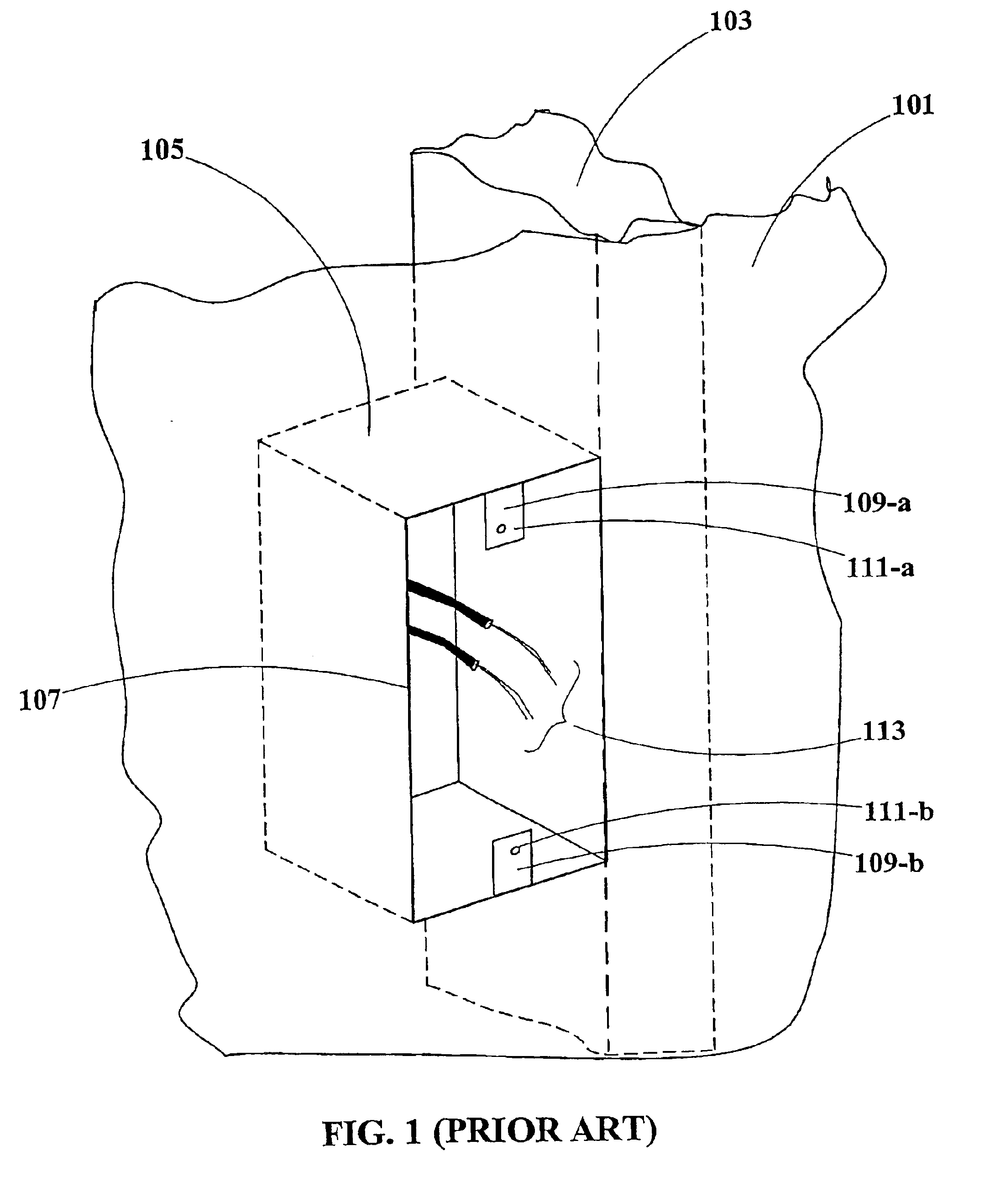
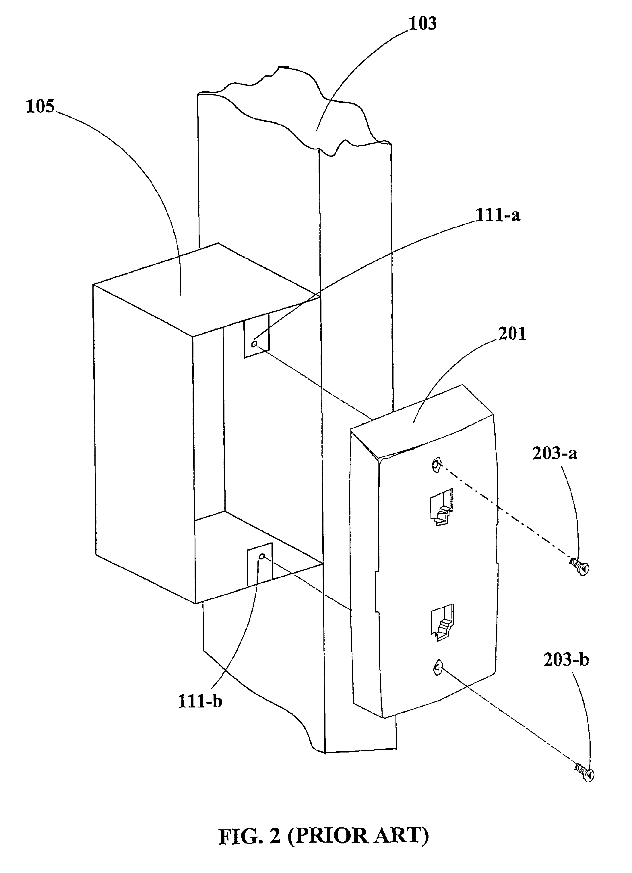
Where this is the case, specialized wall mounting fixtures and faceplates cannot easily be installed in buildings whose construction utilizes the cylindrical cavity and sleeve style of wall mounting without expensive and unsightly external retrofitting of junction boxes 105 within the smaller cavities 303 provided for the sleeves 305, and therefore the utility provided by such specialized wall mounting fixtures and faceplates is difficult and expensive to provide for those buildings.

Method used


Image

  • Adapter for mounting a faceplate of a first style on to an electrical outlet cavity of a second style
  • Adapter for mounting a faceplate of a first style on to an electrical outlet cavity of a second style
  • Adapter for mounting a faceplate of a first style on to an electrical outlet cavity of a second style

Examples


Embodiment Construction

[0034]The principles and operation of an adapter according to the present invention may be understood with reference to the drawings and the accompanying description, wherein components that are common to different embodiments are referenced by identical reference numerals.

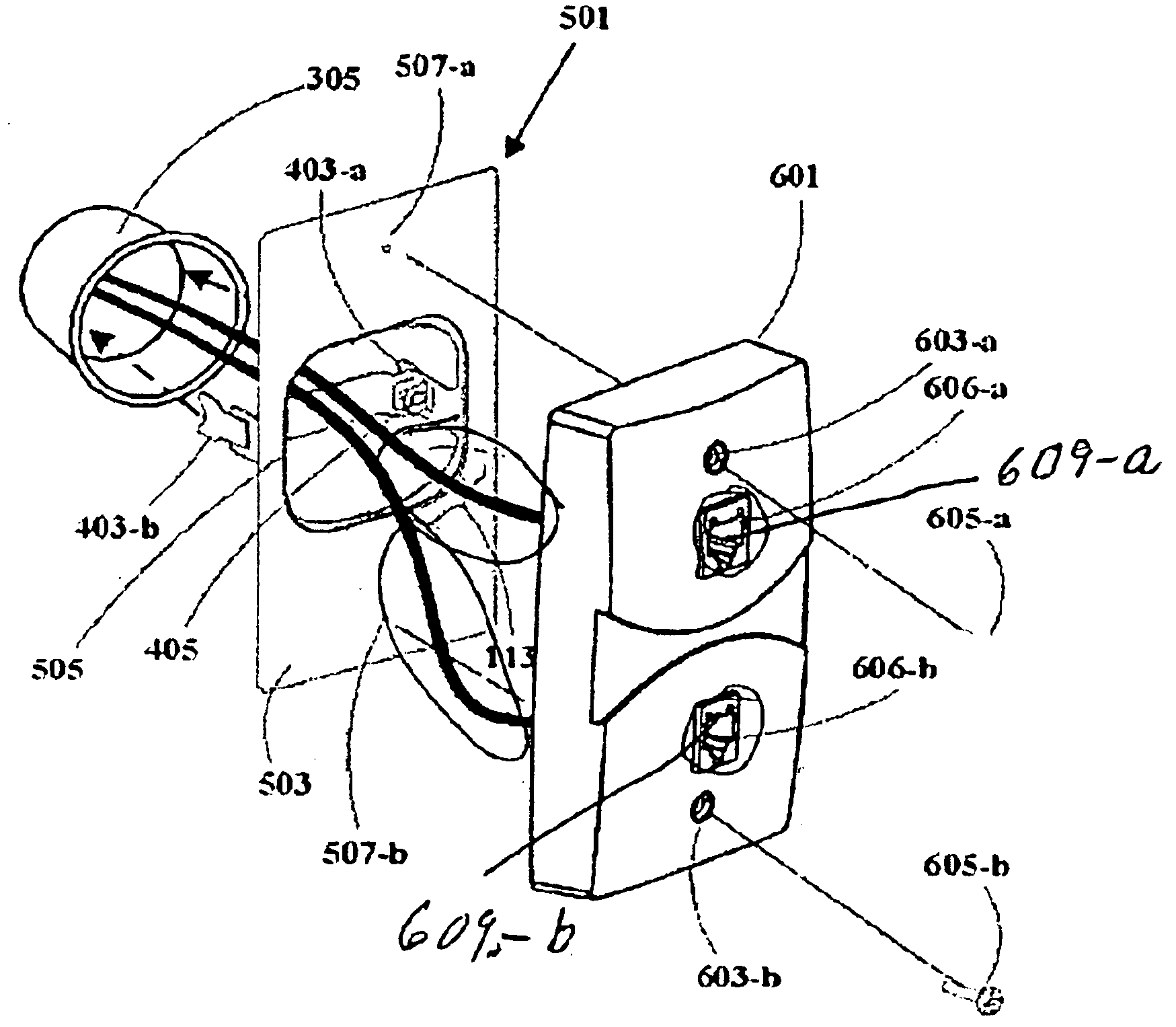
[0035]FIG. 5 illustrates an adapter 501 having a rectangular plate 503 with an opening 505 for passing media 113 (FIG. 3) therethrough and having expandable clamps 403-a and 403-b for gripping to the interior surface of a wall cavity or sleeve. A screw 405 expands clamp 403-a, and a similar screw (not shown) expands clamp 403-b. Mounting points 507-a and 507-b permit attachment of a faceplate designed for the junction box style of wall mounting. Accordingly, the nominal center distance between mounting points 507-a and 507-b is substantially three and one-quarter (3¼) inches. Non-limiting examples of mounting points 507-a and 507b include holes and posts, which may be threaded as well as friction or snap-fit

[0036]...


PUM


Abstract

An adapter for mounting electrical outlet faceplates designed for mounting on rectangular junction boxes in hollow walls onto solid walls with cylindrical cavities and sleeves. Junction box mounting is popular in North America, whereas cavity mounting is popular in Europe and the Middle East. Such an adapter provides universal mounting for specialized faceplates which are designed and intended for junction box mounting. The adapter features clamps for gripping the inner surface of a wall cavity or sleeve and a rectangular plate for mounting an faceplate designed for junction box mounting. The rectangular plate has mounting points with a nominal center-to-center distance of 3à inches, corresponding to the requirements of junction box mounting.

Description

FIELD OF THE INVENTION[0001]The present invention relates to a mechanical mounting adapter for electrical fixtures and the like, and, more particularly, to a wall mounting adapter for outlets and similar fixtures.BACKGROUND OF THE INVENTION[0002]Wall outlets for electrical apparatus and the like are in widespread use, allowing convenient connection of devices such as electrical appliances, telephones, cable television receivers, and computers to electrical power mains and communication networks. In addition, similar fixtures are often attached to walls, floors, and ceilings, and are connected in like manner to electrical power and communications networks. The term “wall” herein denotes any fixed surface to which socket outlets are commonly connected and includes, without limitation, walls of a building or similar structure regardless of orientation (including, but not limited to vertical walls, as well as floors and ceilings), as well as surfaces of other structures to which socket ...

Claims


Application Information

Patent Timeline
Patent Type & Authority Patents(United States)
IPC IPC(8): H02G3/14H01H9/02H01R31/02H02G3/02
CPCH02G3/126H02G3/14
Inventor BINDER, YEHUDAHAZANI, AMI
Owner CONVERSANT INTPROP MANAGEMENT INC
Learn More