

Video coding method and apparatus for calculating motion vectors of the vertices of a patch of an image and transmitting information of horizontal and vertical components of the motion vectors
Inactive Publication Date: 2005-08-09
HITACHI LTD
View PDF12 Cites 10 Cited by
- Summary
- Abstract
- Description
- Claims
- Application Information
AI Technical Summary
Benefits of technology
[0041]An object of the present invention is to realize a motion estimation process with a small amount of computations by reducing the number of calculations for interpolation of luminance values.
[0042]Another object of the invention is to provide a method of reducing the computation accuracy required for computing the transformation function at the time of synthesizing a predicted image P and also preventing the mismatch between the predicted images P attributable to the computation accuracy of the transformation function.
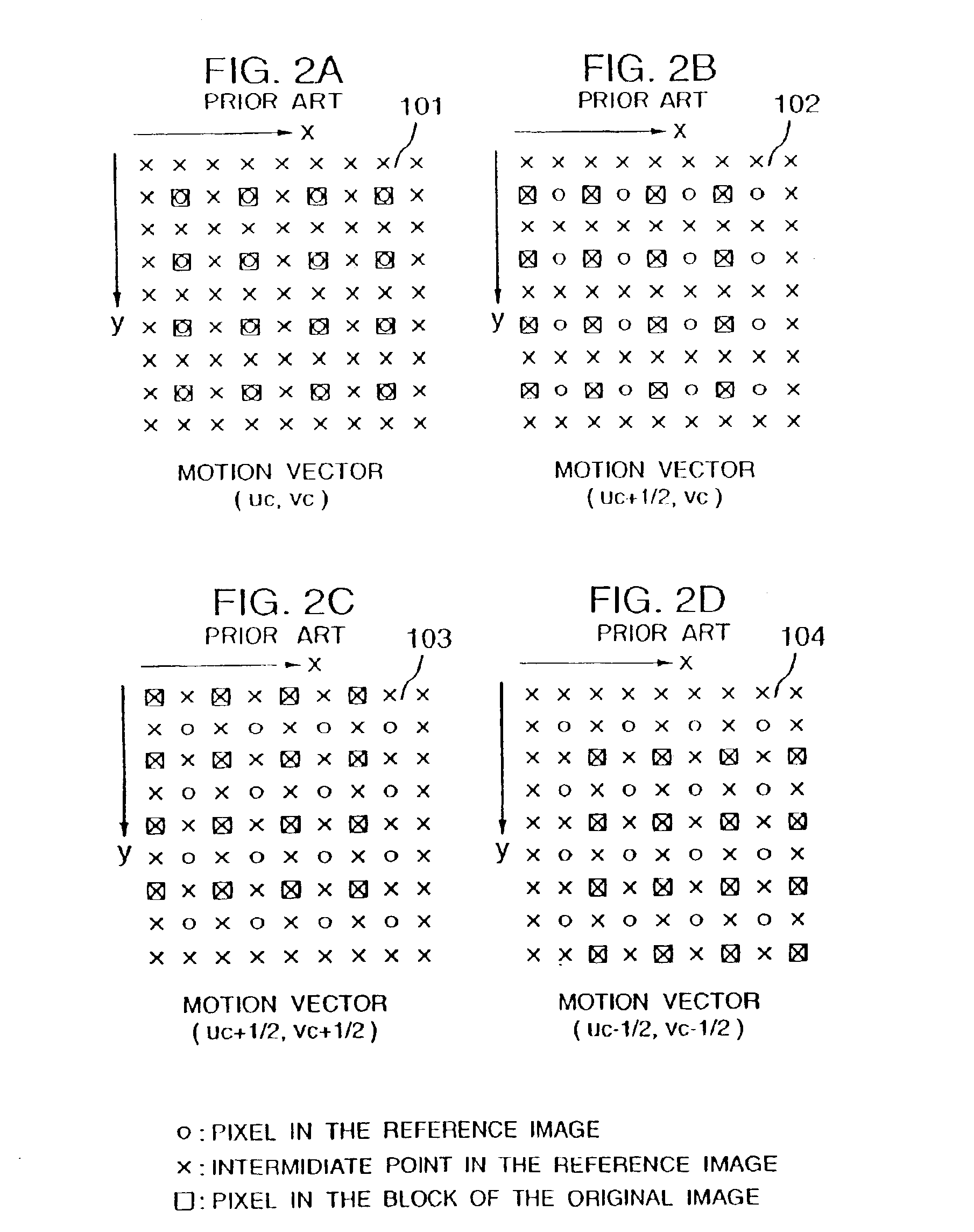
[0043]Prior to motion estimation, a high-resolution reference image R′ is prepared for which the luminance value of a point having x and y coordinates equal to an integral multiple of 1 / m1 and 1 / m2 (m1 and m2 are positive integers) respectively is determined by interpolation on the reference image R. It follows therefore that in the high-resolution reference image R′, pixels exist at points whose x and y coordinate values are an integral multiple of 1 / m1 and 1 / m2 respectively. In the case where the luminance value of the reference image R at a position having a coordinate value other than an integer becomes required in the process of motion estimation, such a value is approximated by the luminance value of a pixel existing at a position nearest to the particular coordinate in the high-resolution reference image R′. The object of reducing the number of interpolation computations thus is achieved.
[0045]Also, assume that the horizontal and vertical components of the motion vector of each pixel used for synthesizing the predicted image P in the video coder and the video decoder are defined to take a value equivalent only to an integral multiple of 1 / d1 or 1 / d2 (d1 and d2 being integers) respectively of the distance between adjacent pixels. The object of reducing the required computation accuracy of the transformation function and preventing a mismatch is thus achieved.
Problems solved by technology
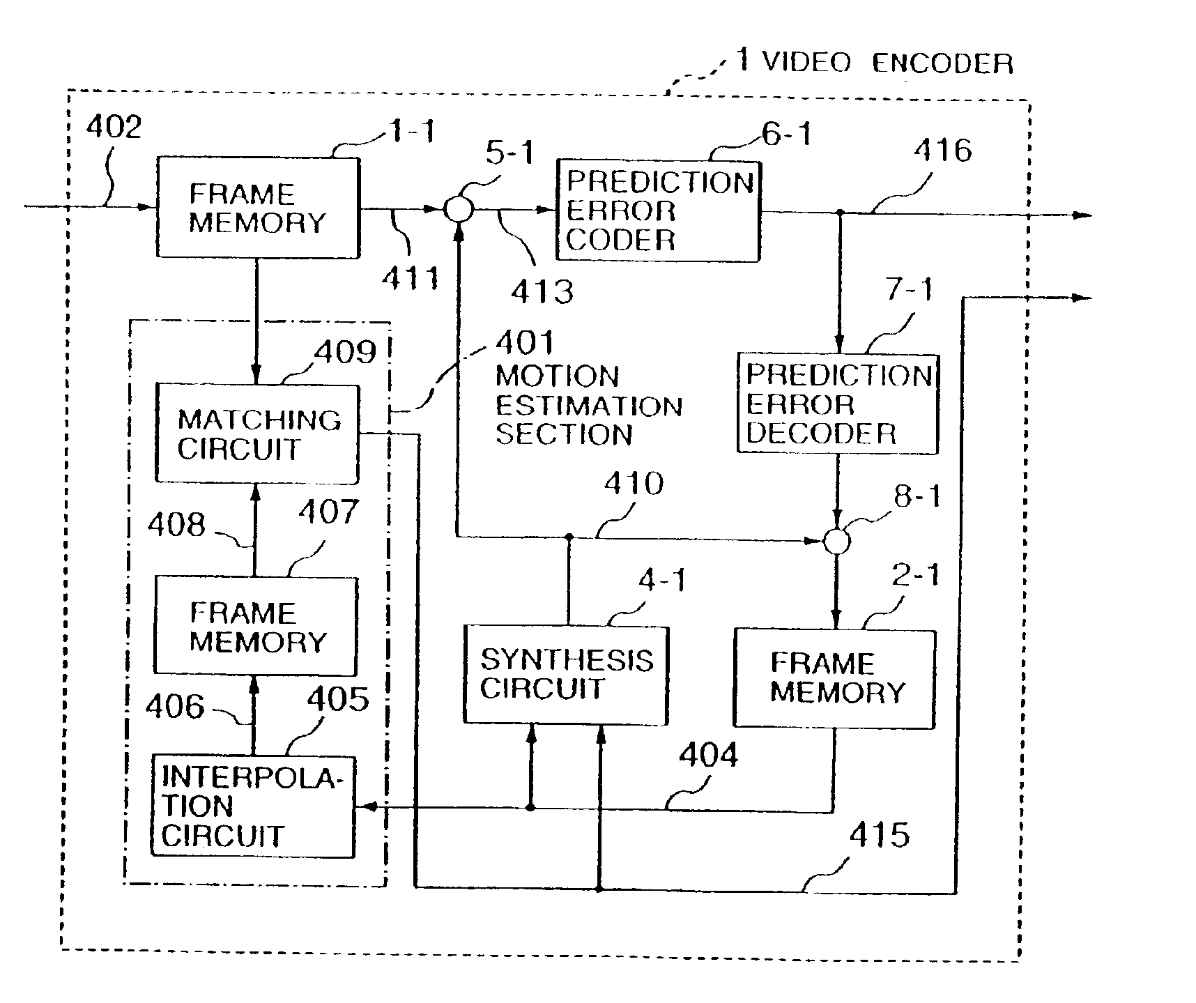
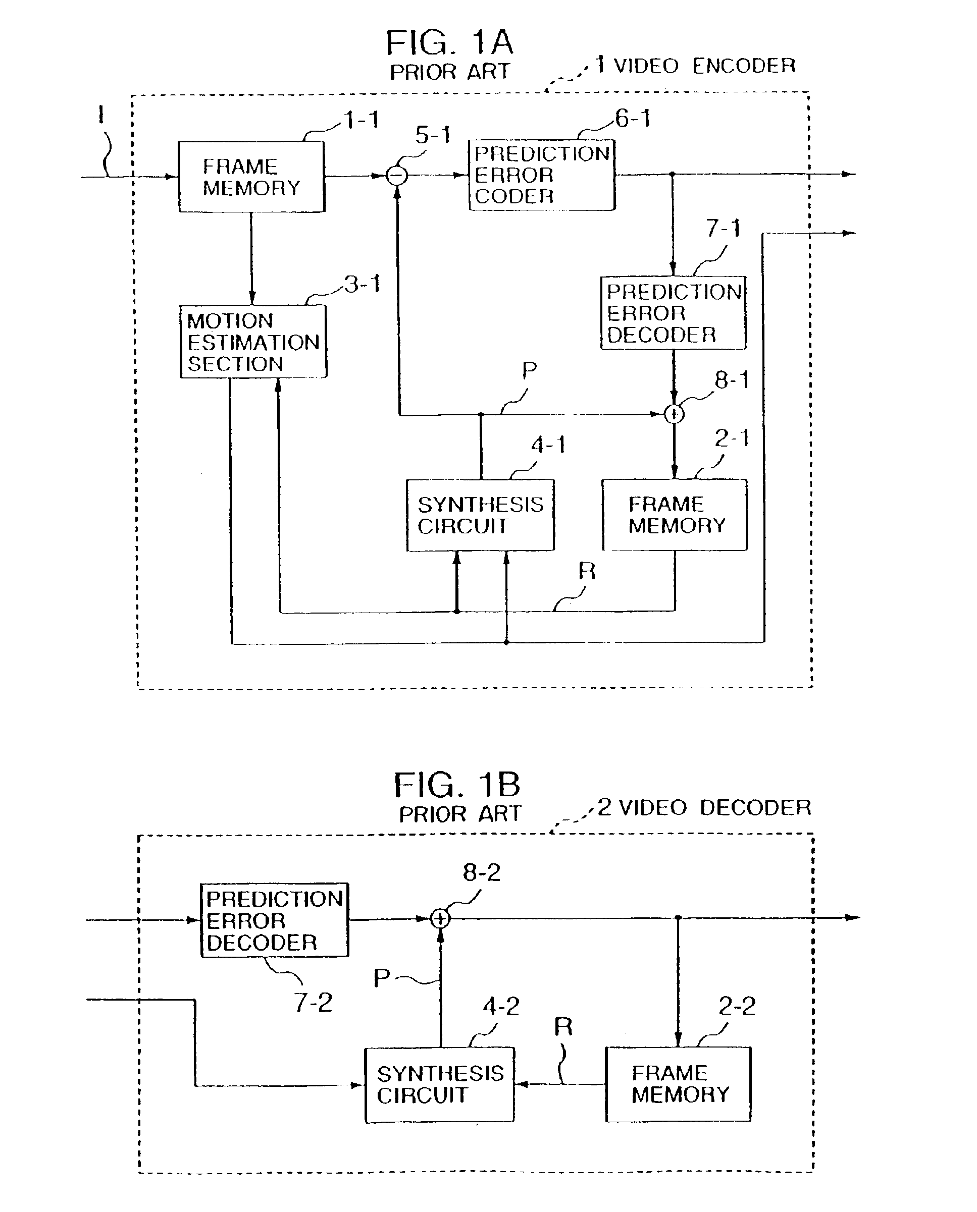
With the “motion compensation based on spatial transformation”, motion estimation based on matching poses the problem of a greatly increased amount of computations required for interpolation of luminance values at points lacking a pixel on the reference image R. A more complicated computation operation is another problem which will be posed if the computation accuracy for synthesizing each predicted image P in the video coder and the video decoder is to be improved to accommodate a mismatch between a predicted image P obtained at the sending end and a predicted image P obtained at the receiving end.
Method used
View moreImage
Smart ImageViewing Examples

Examples
Embodiment Construction
[0063]A method of performing the motion estimation operation by improving the resolution of the whole reference image R in a video coder 1 will be explained as a first embodiment. First, the luminance value of a point lacking a pixel on the reference image R is interpolated to form a high-resolution reference numeral R′. Assuming that the bilinear interpolation (Equation 3) is used as an interpolation scheme for the luminance value, the high-resolution reference numeral R′ is given by Equation R′(x+sm1,y+tm2=(1-tm2){(1-sm1)R(x,y)+sm1R(x+1,y)}+tm2{(1-sm1R(x,y+1)+sm1R(x+1,y+1)}(8)
where it is assumed that s and t are an integral number and that 0≦s
[0064]In the desc...
Login to View More PUM
 Abstract
A method and apparatus for coding an image includes calculation of motion vectors of vertices of a patch in an image being encoded and transmitting information of horizontal and vertical components of the motion vectors of the vertices and information specifying that values of the horizontal and vertical components of a motion vector for each pixel in the patch are integral multiples of 1 / d of a distance between adjacent pixels, where d is an integer not less than 2.
Description
[0001]This is a continuation of application Ser. No. 09 / 994,728, filed Nov. 28, 2001 now U.S. Pat. No. 6,542,548; which is a divisional application of application Ser. No. 09 / 863,428, filed May 24, 2001 now U.S. Pat. No. 6,516,033; which is a divisional of application Ser. No. 09 / 626,788, filed Jul. 26, 2000, now U.S. Pat. No. 6,285,713; which is a continuation of application Ser. No. 09 / 364,255, filed Jul. 30, 1999, now U.S. Pat. No. 6,134,271; which is a continuation of application Ser. No. 08 / 903,199, filed Jul. 15, 1997, now U.S. Pat. No. 5,963,259; which is a continuation of application Ser. No. 08 / 516,218, filed Aug. 17, 1995, now U.S. Pat. No. 5,684,538.BACKGROUND OF THE INVENTION[0002]1. Field of the Invention[0003]The present invention relates to a video coding / decoding system and a video coder and a video decoder used with the same system for implementing a motion compensation method in which all the pixels associated with the same patch are not restricted to have a common...
Claims
Login to View More Application Information
Patent Timeline
 IPC IPC(8): G06T9/00H04N7/26H04N5/14H04N7/12
CPCH04N19/61H04N19/43H04N19/53H04N19/54H04N19/523H04N5/145
InventorNAKAYA, YUICHIROKIMURA, JUNICHI
OwnerHITACHI LTD