Microwave powered lamphead having external shutter

Active Publication Date: 2005-08-23
NORDSON CORP
View PDF6 Cites 12 Cited by
  • Summary
  • Abstract
  • Description
  • Claims
  • Application Information

AI Technical Summary

Benefits of technology

[0006]The invention generally provides a microwave powered lamp assembly having at least one microwave powered lamp bulb mounted in an optical cavity. A shutter system is provided to selectively open and closed the optical cavity and correspondingly allow and prevent light transmission to a target. A tight seal against light transmission is achieved in the closed position. Thus, the lamp bulb may remain on or powered while the shutter is actuated between a position which allows the transmission of light from the optical cavity and a position which prevents any significant transmission of light from the optical cavity. The shutter can allow much quicker cycling of the lamp between an active or curing state and an inactive or noncuring state. In addition, the material forming the shutter substantially prevents transmission of any light from the optical cavity through that material,

Problems solved by technology

Finally, while microwave powered lampheads are faster to cycle on and off than electrode powered lampheads, they may still not cycle on and off quickly enough to achieve a desired production speed.
Unfortunately, even microwave po

Method used


Image

  • Microwave powered lamphead having external shutter
  • Microwave powered lamphead having external shutter

Examples


Example

DETAILED DESCRIPTION OF THE DRAWINGS

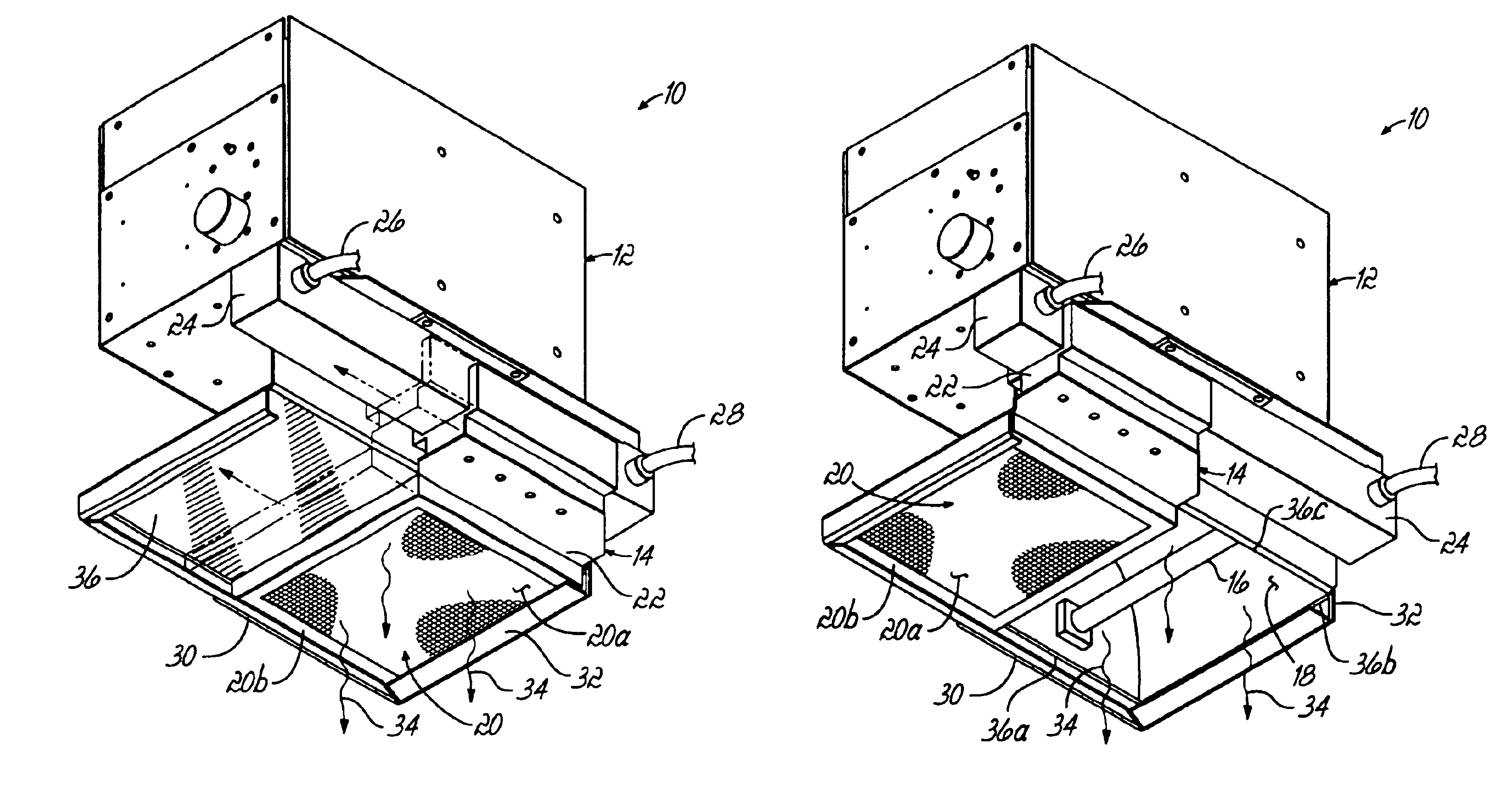
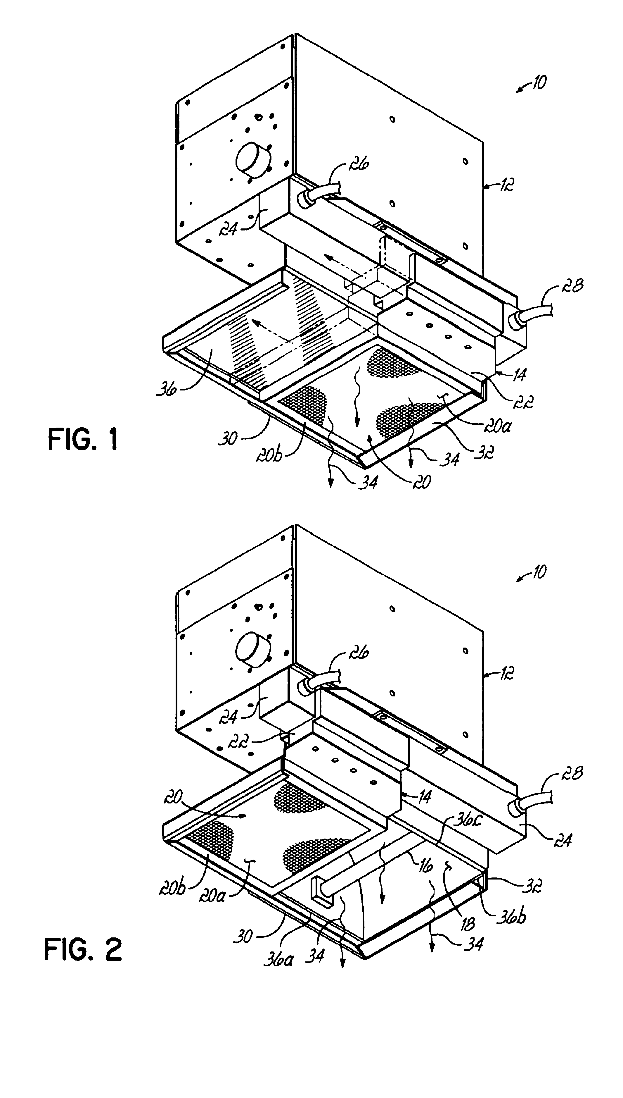
[0011]Referring to FIGS. 1 and 2, a lamphead 10 constructed in accordance with the inventive principles generally comprises a magnetron and control housing 12 coupled with a shutter assembly 14. At least one magnetron (not shown) is operatively associated with a plasma-filled lamp bulb 16 contained in an optical cavity 18. Cavity 18 can have conventional reflector structure, such as an elliptical reflector. The magnetron or magnetrons and other control components contained in housing 12 may be conventional and, therefore, further description of these components is not necessary. Shutter assembly 14 further comprises a shutter 20 formed from a louvre material 20a contained in a suitable outer frame 20b. Louvre material 20a may be obtained from Tuttle and Bailey, located in Richardson, Tex. Frame 20b is coupled to a bracket 22 which, in turn, is operatively coupled to a pneumatic, reciprocating actuator 24. Pneumatic actuator 24 may be a conventiona...


PUM


Abstract

A microwave powered lamp head assembly includes a shutter assembly which may be activated to selectively allow transmission of light from the microwave powered lamp bulb. The shutter assembly allows unrestricted airflow when it is in the closed position so that the active lamp bulb may still be cooled, while preventing the transmission of UV radiation through the shutter. The shutter assembly is in close sealing relation with respect to the optical cavity holding the lamp bulb when in the closed position to minimize the escape of UV radiation.

Description

CROSS REFERENCE TO RELATED APPLICATIONS[0001]This application claims the benefit of U.S. Provisional Application No. 60 / 450,308, filed Feb. 27, 2003, the disclosure of which is hereby incorporated by reference herein in its entirety.FIELD OF THE INVENTION[0002]The present invention relates generally to microwave powered UV lamps used for curing various materials by photopolymerization and, more specifically, to manners of quickly cycling the devices between active and inactive states.BACKGROUND OF THE INVENTION[0003]Ultraviolet radiation or UV radiation is often used to photochemically polymerize or cure various types of materials on substrates and may be used in other applications. Existing technology for performing this type of polymerization usually comprises either an electrode-powered ultraviolet lamp or a microwave-powered ultraviolet lamp. The electrode or microwave power is dissipated in a plasma-filled lamp bulb. The plasma radiates light at the desired wavelength or wavele...

Claims


Application Information

Patent Timeline
IPC IPC(8): F21V14/00G02B26/00H01J25/00H01J25/50H05B41/24B01J19/12B05D3/06G21K5/02H01J5/02H01J5/18H01J65/04H05B6/80H05B41/28H05G2/00H05H1/30
CPCB01J19/124G21K5/02H01J65/044H05B41/2806B01J2219/0877B05D3/067Y02B20/22Y02B20/00
Inventor BORSUK, JAMES M.MCGHEE, EDWARD C.
Owner NORDSON CORP
Why Eureka
Try Eureka