Ultraviolet-light-based disinfection reactor

a disinfection reactor and ultraviolet light technology, applied in the field of disinfection apparatus, can solve the problems of reducing the effective flow throughput of such arrangements, increasing the initial cost and operating costs of such arrangements, and the long treatment system that is difficult to incorporate as a retrofit for an existing water treatment system, so as to achieve the effect of improving the disinfection

Inactive Publication Date: 2005-09-06
CALGON CARBON
View PDF0 Cites 49 Cited by
  • Summary
  • Abstract
  • Description
  • Claims
  • Application Information

AI Technical Summary

Benefits of technology

[0010]In accordance with another aspect of the present invention the guide surfaces are convexly-curved and are spaced from and opposed to each other to define a flow channel therebetween, wherein the flow channel includes a reduced-area throat section. At least one ultraviolet lamp is disposed upstream of the reduced-area throat and at least one ultraviolet lamp is disposed downstream of the throat. Liquid flowing through the flow channel passes over and around each of the ultraviolet lamps to expose the liquid to ultraviolet light to thereby inactivate microorganisms to disinfect liquid that flows through the flow channel.

Problems solved by technology

'229 patent requires a lengthy treatment system, because of the alignment of the tubular lamps with the flow, that limits the adaptability of that arrangement as a retrofit for existing treatment plants, and it also utilizes a large number of ultraviolet lamps, which increases both the initial cost as well as the operating costs for such a system.
That arrangement also involves a lengthy treatment system that is difficult to incorporate as a retrofit for an existing water treatment system.
The Free '800 apparatus is intended for use in waste water treatment systems, in which the transmittance of the water is of the order of only about 20%, and thus especially narrow confinement of the untreated water about the lamp tubes is necessary, thereby reducing the effective flow throughput in such arrangements.

Method used


Image

  • Ultraviolet-light-based disinfection reactor
  • Ultraviolet-light-based disinfection reactor
  • Ultraviolet-light-based disinfection reactor

Examples


Embodiment Construction

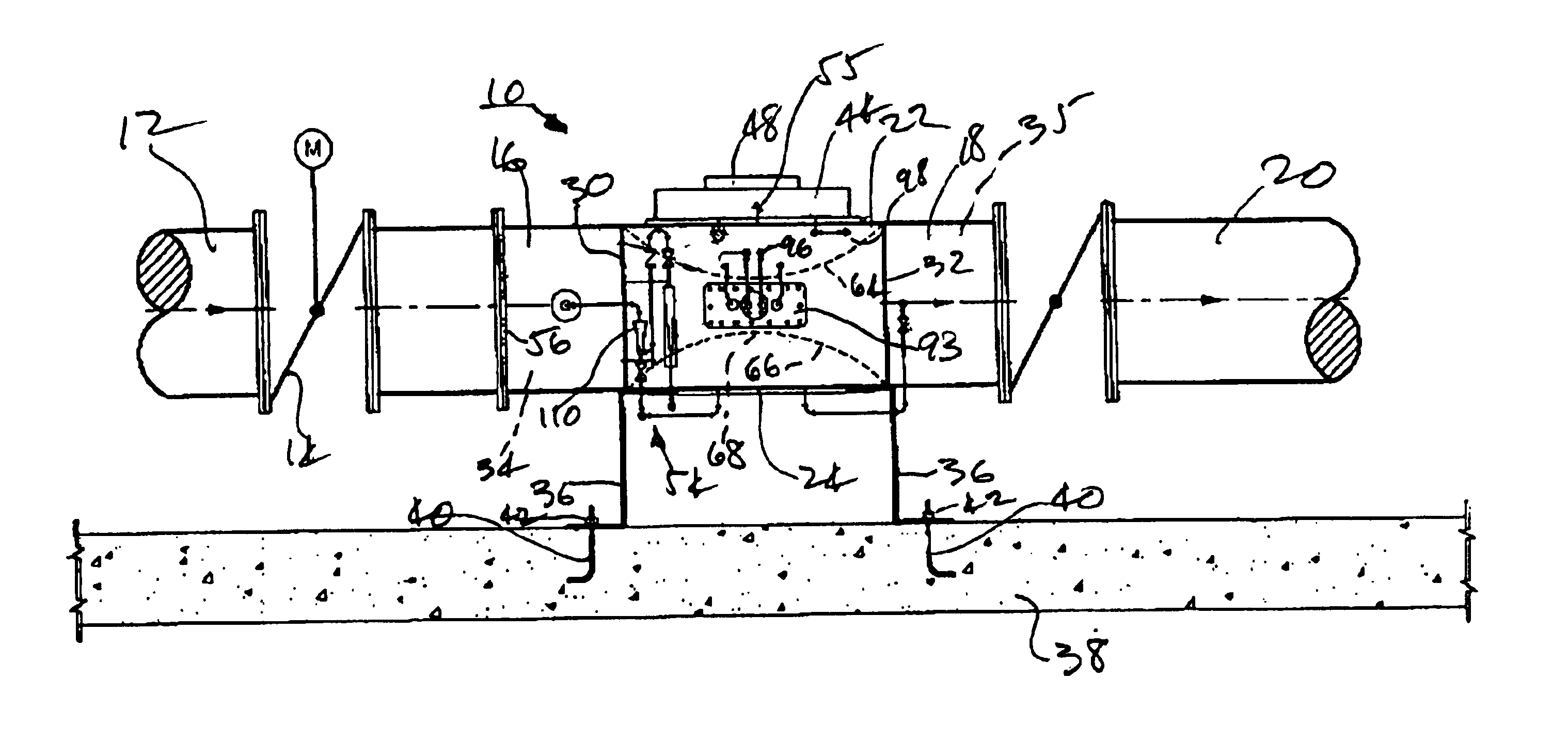
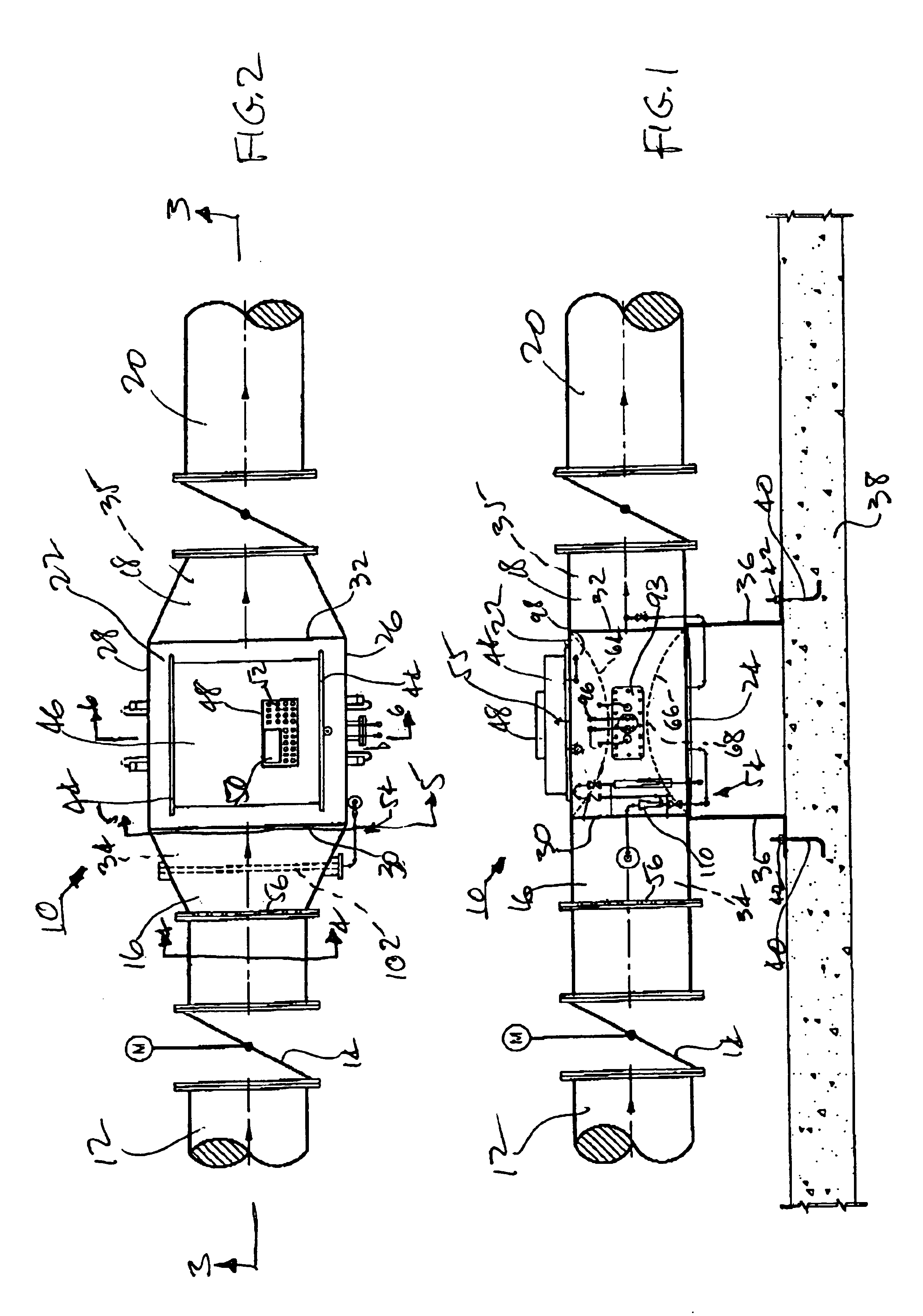
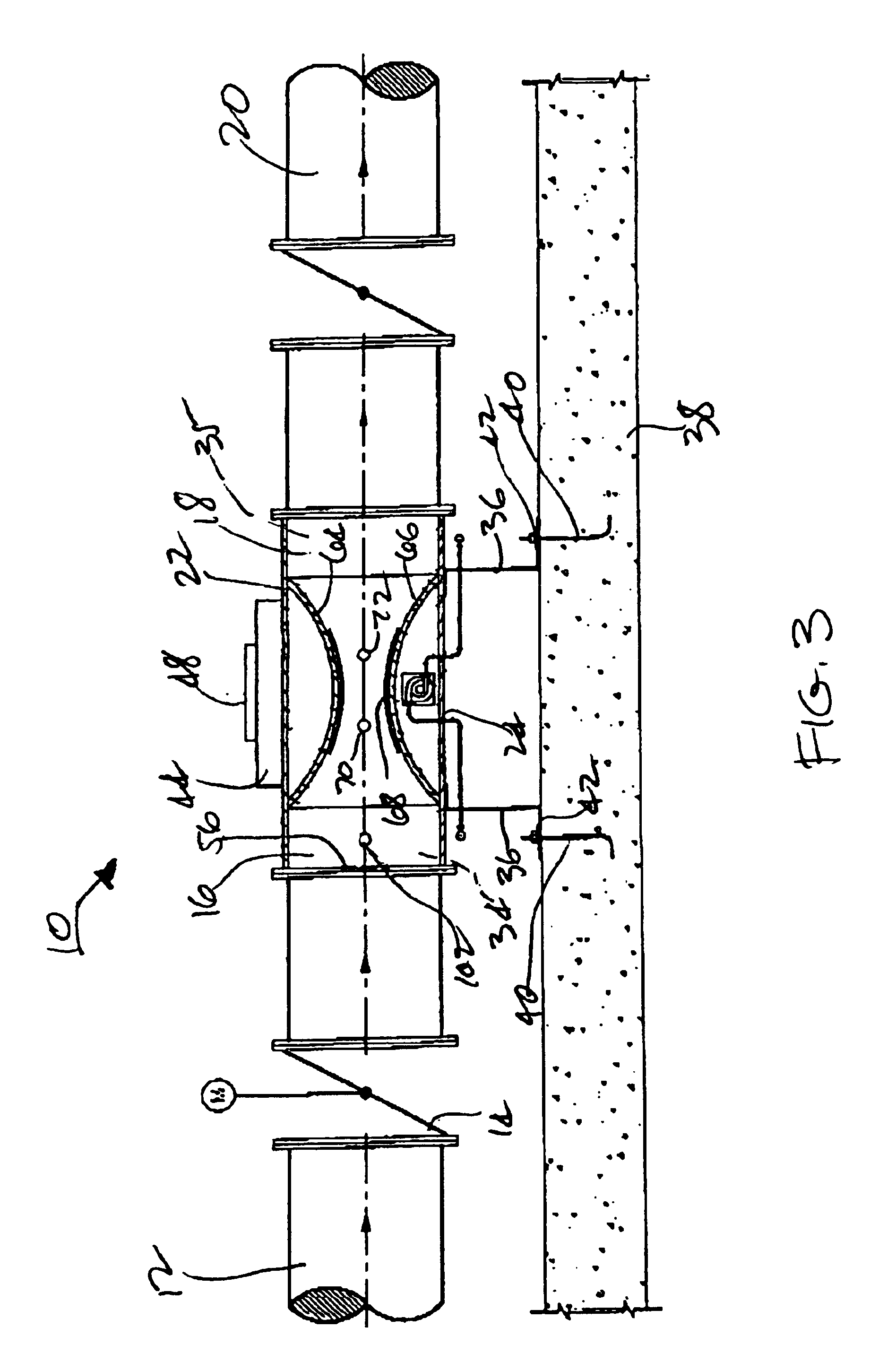
[0038]Referring now to the drawings, and particularly to FIGS. 1, 2, and 3 thereof, there is shown a disinfection reactor vessel 10 positioned in a pipeline 12 that would typically be located in a filter pipe gallery of a water treatment plant (not shown). For example, pipeline 12 can carry water that flows from the outlet of a gravity water filter in a water treatment plant. Pipeline 12 can have the same diameter as the filter outlet opening, which typically ranges from 6 to 36 inches, depending upon the design flow rate, and, as shown, it can include a motor-operated butterfly valve 14 for controlling the rate of flow within pipeline 12, and thereby also the rate of flow of water into and through reactor vessel 10.

[0039]Pipeline 12 from the water treatment plant is connected with a reactor-vessel inlet conduit 16 by a flanged connection, or the like. A reactor-vessel outlet conduit 18 carries away treated water that has passed through the disinfection reactor vessel and that has b...


PUM

PropertyMeasurementUnit
surface reflectanceaaaaaaaaaa
transmittanceaaaaaaaaaa
diameteraaaaaaaaaa

Abstract

A disinfection reactor for disinfecting liquid, such as water from a water filtration plant, by exposing the liquid to ultraviolet light. The reactor includes a generally rectangular reactor vessel and two or more medium pressure ultraviolet lamps that extend within the reactor vessel in a direction transverse to the direction of liquid flow therethrough. The reactor vessel includes liquid guide surfaces that guide liquid to flow in a converging flow path having a reduced-area flow region in the vicinity of the ultraviolet lamps. The ultraviolet lamps are positioned spaced from and between the guide surfaces.

Description

CROSS-REFERENCE TO RELATED APPLICATION[0001]The present application is a continuation-in-part of application Ser. No. 09 / 805,799, filed Mar. 15, 2001, now abandoned, the entire disclosure of which is hereby incorporated herein by reference.BACKGROUND OF THE INVENTION[0002]1. Field of the Invention[0003]The present invention relates to disinfection apparatus for use in connection with water treatment plants and involves the use of ultraviolet light for inactivating microorganisms. More particularly, the present invention relates to an improved ultraviolet-light-based disinfection reactor for treating water and that utilizes medium pressure ultraviolet lamps for microorganism treatment, either alone or as supplemented by a chemical oxidation treatment that can be included within the apparatus.[0004]2. Description of the Related Art[0005]Ultraviolet-light-based apparatus for disinfecting water by subjecting the water to ultraviolet light to inactivate microorganisms has been known for ...

Claims


Application Information

Patent Timeline
Patent Type & Authority Patents(United States)
IPC IPC(8): B01J19/12G01N21/01C02F1/00C02F1/32C02F1/72
CPCC02F1/325C02F1/722C02F2201/3228C02F2201/324C02F2201/326C02F2201/328C02F2209/005C02F2209/40
Inventor SCHULZ, CHRISTOPHER R.
Owner CALGON CARBON
Why Eureka
Try Eureka